Project 3
Contents
Introduction
The goal of project 3 is to use the sensors and actuators from project 1, the real time operating system (RTOS) from project 2, and an iRobot Roomba to create a semi-autonomous laser tank capable of battling other tanks. The Roomba will be controllable through a joystick and a pushbutton for the laser. It can roam and avoid obstacles and virtual walls on its own in autonomous mode. There is also a light-sensing target on the Roomba that detects when it has been shot, in which in case it will remain stationary, as if it has been destroyed.
Hardware
iRobot Roomba Create 2
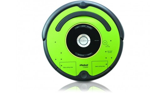
The iRobot Roomba Create 2 is a mobile programmable robot that allows sounds, movements, and additional sensors and actuators to be added and customized.
Design
This section talks about the system design from a high level perspective using block diagrams, finite state machines, and the subsumption architecture.
System Architecture
Base Station
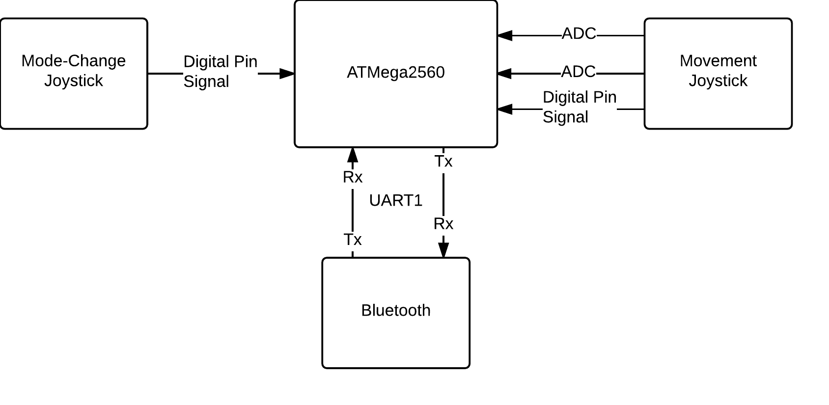
The base station is connected to bluetooth, and two joysticks. Bluetooth provides bidirectional communication and is used to communicate with the remote station over UART. One of the joysticks is used to control the Roomba, with its pushbutton to fire the laser. The second joystick is purely used for the pushbutton to change the remote station's state from manual to semi-autonomous and vice versa. This is illustrated in the base station's block diagram:
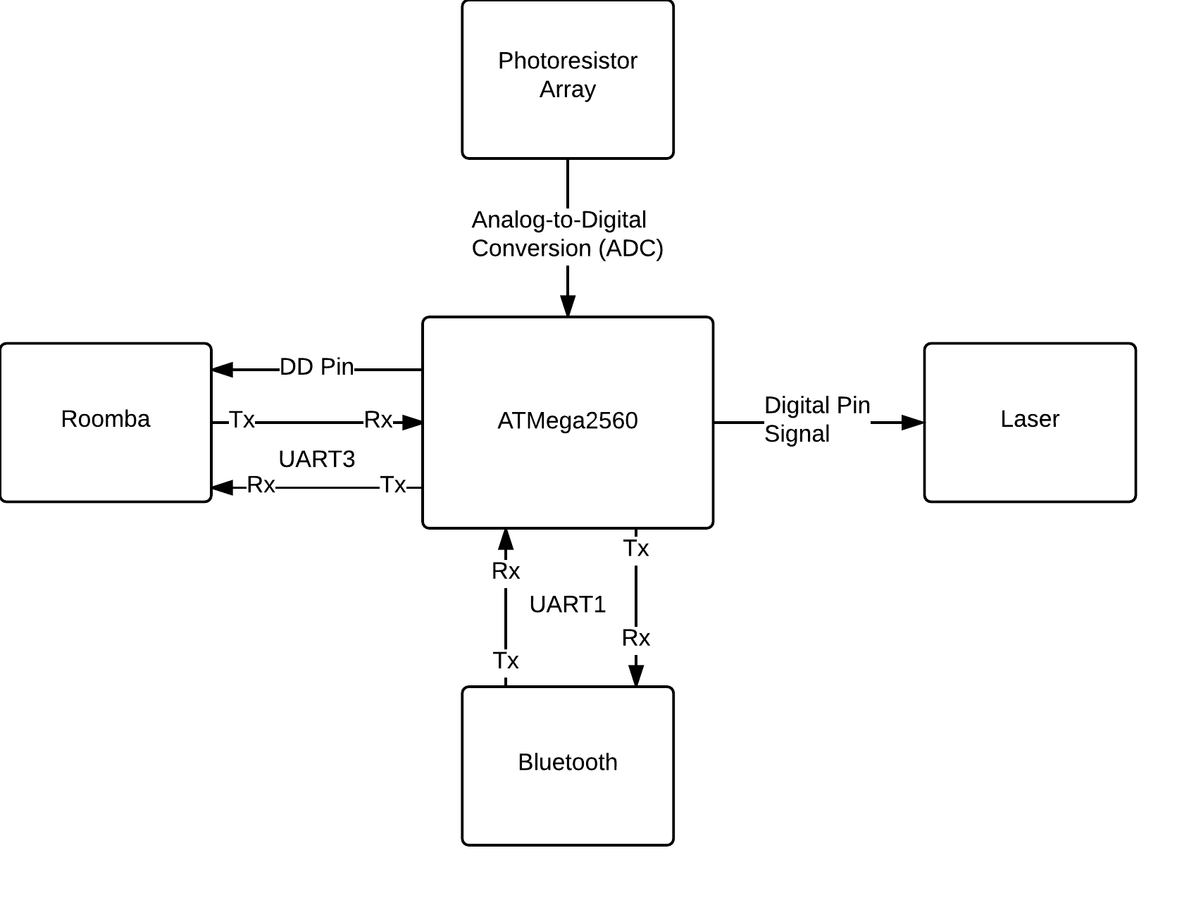
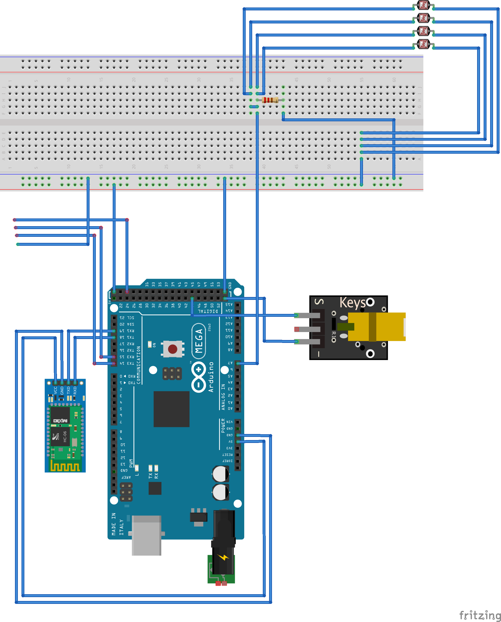
The remote station is connected to bluetooth, the laser, the photocell array, and the Roomba, which it is mounted on. The laser emits a bright beam when the pin is set high. The photocell is read to obtain a value and determine if it has been shot, and the connection to the Roomba allows the remote station to send the Roomba commands, and receive sensor data back. The block diagram below shows the architecture of the remote station.
Phase 1: Manual Control
Phase 1 is heavily associated with behaviour based robotics. The sensors are used to directly control the actuators.
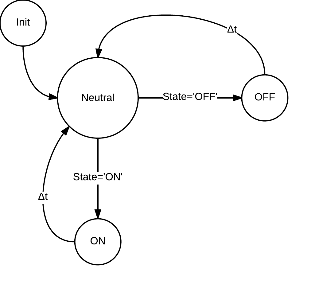
Laser FireThe Fire FSM takes data from a pushbutton and turns the laser on if the state of the pushbutton is down, or off if the state is up. The following shows the connection of sensors to actuators and the finite state machine (FSM).

 Photocell
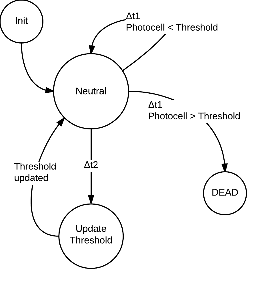
The photocell sensor array detects spikes in light to determine if it has been shot. Every 0.5 seconds it will update a threshold value. This threshold value is the amount of light coming from the room plus a small value. If this threshold is exceeded, then we can determine that the tank has been shot. Being shot puts the Roomba into a dead state where it can't move or shoot. This is illustrated in the diagrams below.

 Movement
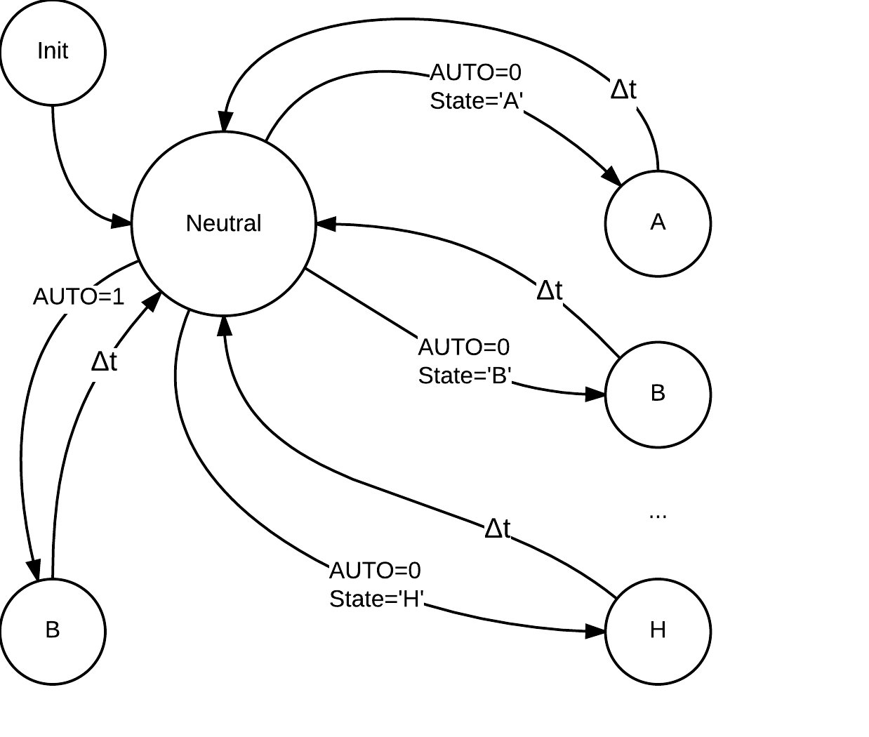
The joystick is used to control the Roomba. The position of the joystick is mapped to nine different states. These states are shown in the diagram below:
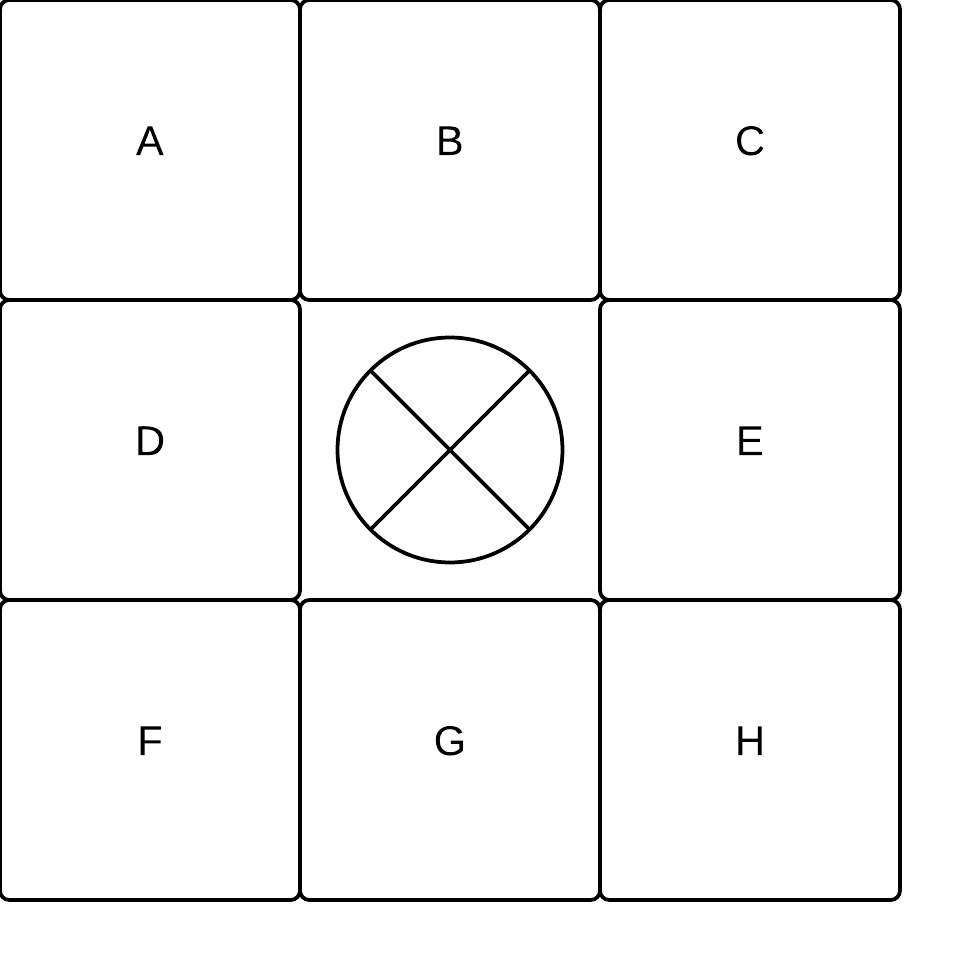 These letters then map to commands:
| A | Forward left |
| B | Forward |
| C | Forward right |
| D | Spin counterclockwise |
| E | Spin clockwise |
| F | Backwards left |
| G | Backwards |
| H | Backwards right |
| X | Stop |

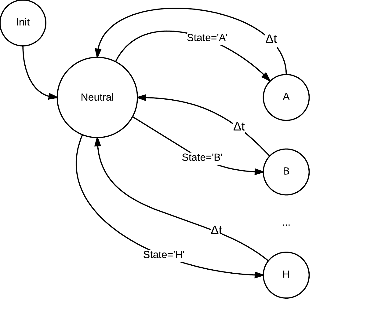 Communication
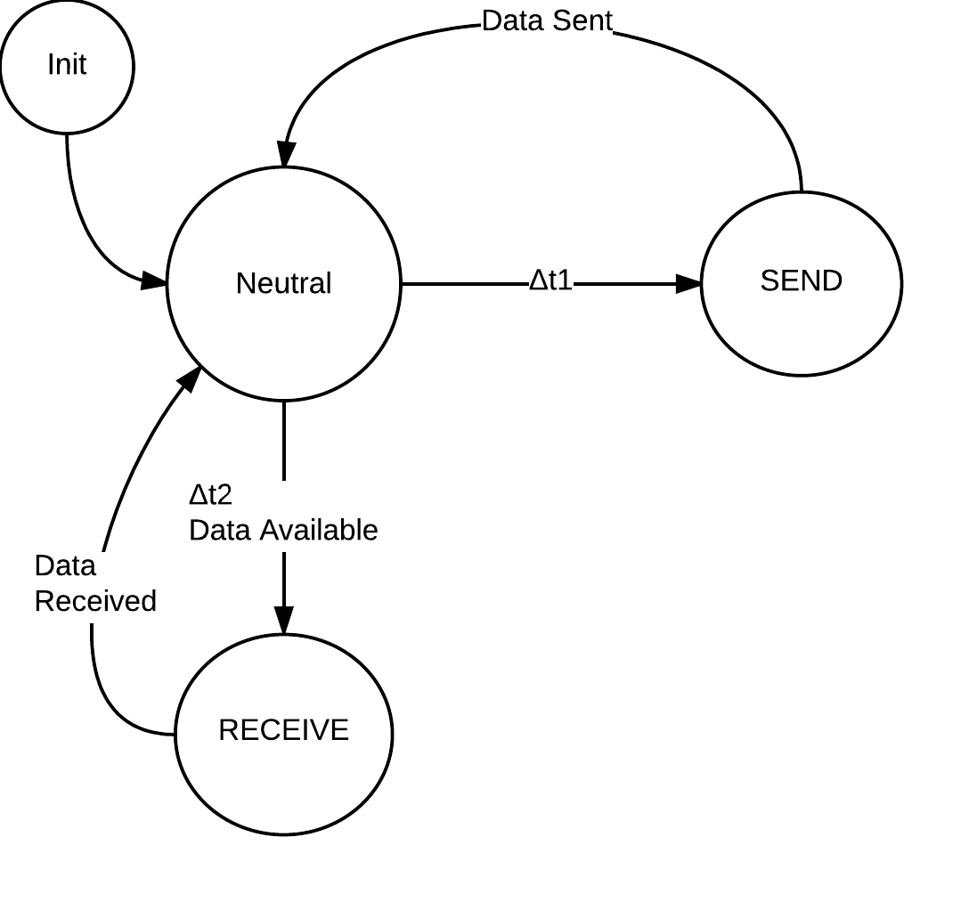
The base station needs to communicate with the remote station, and the remote station needs to communicate with both the base station and the Roomba. This is done through UART communication over USB and bluetooth. All stations can send data and receive data. This is shown in the FSM below:
Phase 2: Semi-Autonomous Control
Subsumption Architecture
Phase 2 uses the subsumption architecture. In this robotics architecture, sensors may cause the system to have different behaviour based on their state. This is accomplished by decomposing the overall behaviour into sub-behaviours. These sub-behaviours implement a degree of behavioral competence. The more important behaviours are then able to subsume less important behaviours. This can be seen from the high-level representation of our system's motor control logic:
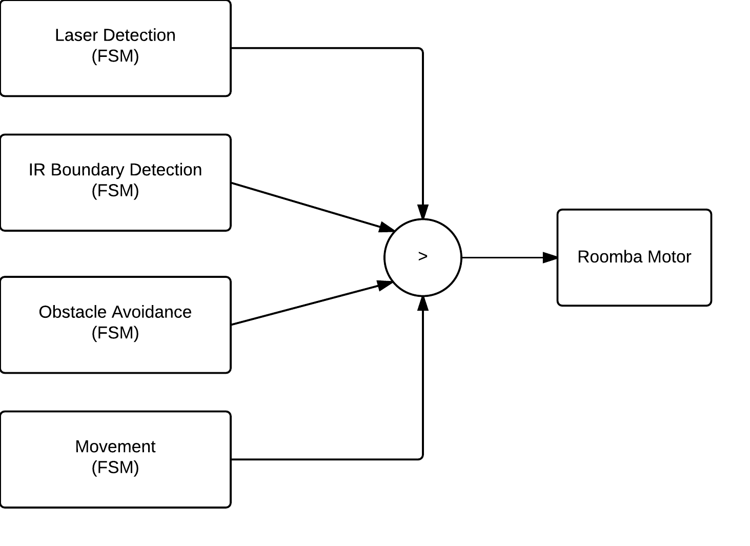 In the above representation, four separate FSM's govern the Roomba's motor behaviour. However, there is a subsumption hierarchy that determines which logic is actually in command. In our system, the order is:
Laser Detection > IR Boundary Detection > Obstacle Avoidance > Movement.
When the Roomba is in semi-autonomous mode, it will travel forward, and when it detects an obstacle or virtual IR wall, it will back up, turn counterclockwise and continue onward.
Updated MovementThe Movement FSM was updated to include a pushbutton input that toggles the state of AUTO between 1 and 0. In addition to the functionality from Phase 1, the system now only continues forward when AUTO is set to 1. The change can be seen in the following diagrams:

 IR-Wall Detection
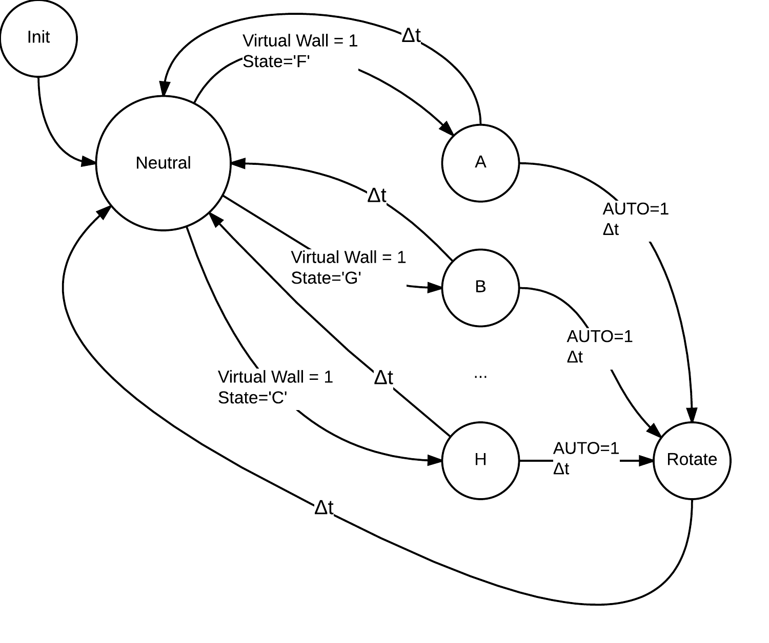
The IR-Wall Detection FSM uses the Roomba sensor data and sends a movement command if an IR-Wall is detected. The command sent depends on the current movement state, and is the reverse of the current movement state. The mapping of current states to movement commands is shown in the table below:
| A | Backwards left |
| B | Backwards |
| C | Backwards right |
| D | Spin clockwise |
| E | Spin counterclockwise |
| F | Forward left |
| G | Forward |
| H | Forward right |
| X | Backwards |

 Obstacle Avoidance
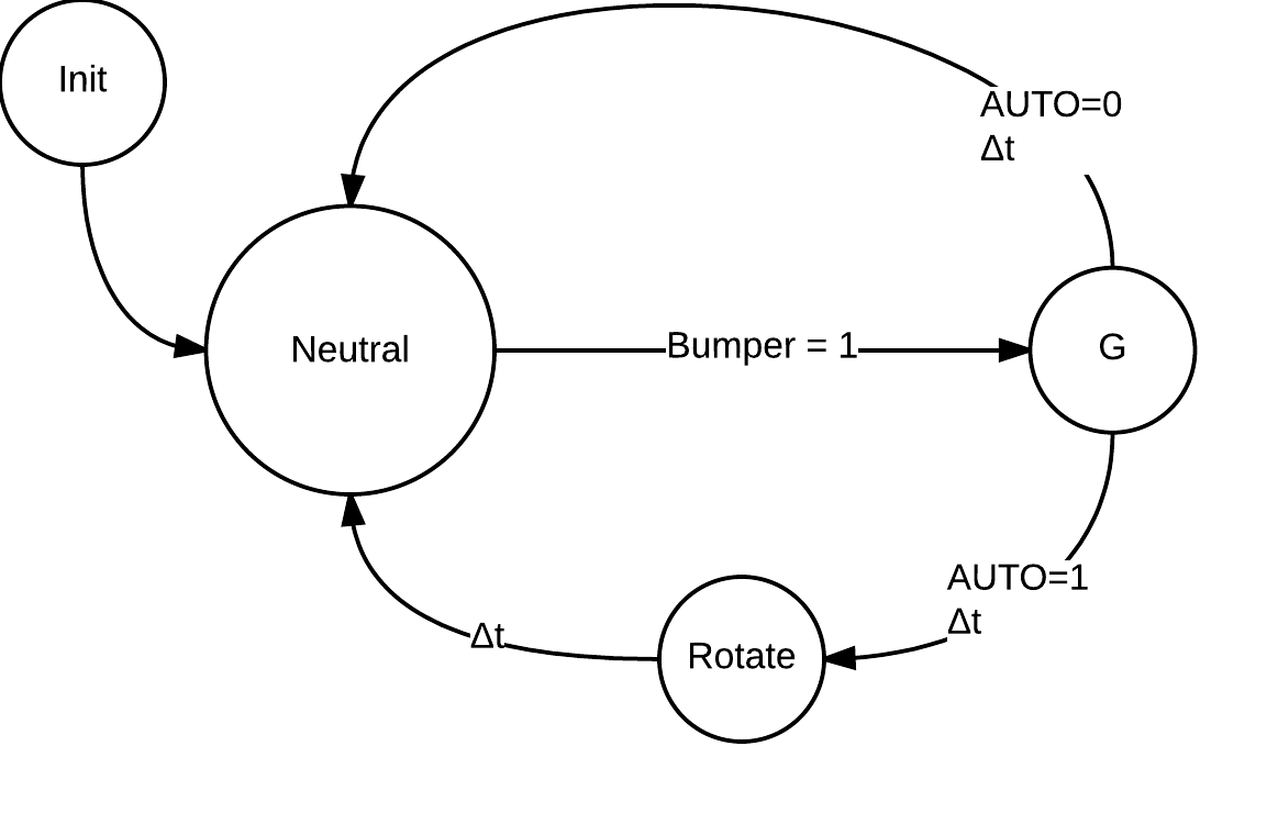
The Obstacle Avoidance FSM takes Roomba sensor data and determines if an obstacle has been hit by the Roomba's front bumpers. If this is the case, the Roomba will drive backwards for 200ms. In addition, if the Roomba is currently in autonomous mode (ie: AUTO = 1), the Roomba will then briefly turn in place. This FSM is shown below:

Task Decomposition
The above functionality is broken down into tasks that will run on the RTOS. Each task has its own scheduling parameters (priority and frequency). A priority of 0 represents the highest, whereas a priority of 10 is the lowest.
Base Station Tasks
| Task | Description | Priority, Frequency |
| SwitchTask | Switches between autonomous and manual mode | 2, 20ms |
| LaserTask | Reads the pushbutton and sends the data to fire the laser | 2, 10ms |
| screenTask | Checks if any data is ready to be displayed on the LCD | 2, 15ms |
| bluetoothReceive | Receives incoming data from the remote station | 2, 15ms |
| RoombaTask | Reads x and y from joystick and maps it to Roomba states | 2, 20ms |
| Idle | Runs when no other task is available | 10, No other taks |
| Task | Description | Priority, Frequency |
| Bluetooth_Receive | Receives incoming data from the base station | 1, 5ms |
| Bluetooth_Send | Sends lightsensor data to the base station | 2, 10ms |
| Laser_Task | Turns the laser on or off depending on the pushbutton | 2, 10ms |
| LightSensor_Task | Reads the lightsensor value to determine if it has been shot | 2, 10ms |
| Roomba_Task | Determines the next move for the Roomba | 2, 20ms |
| Get_Sensor_Data | Requests bumper and virtual wall data from the Roomba | 2, 20ms |
| Idle | Runs when no other task is available | 10, 10, No other taks |
Implementation
RTOS
The RTOS from project 2 is running on both the base and remote stations. The stations do not use all of the features of the RTOS, but they use task creation, sleep, termination, os abort, and mutex lock and unlock. Thus the code does have critical sections that are protected by mutexes, and tasks that are put to sleep and woken up.
UART
The UART library is used to transfer data across bluetooth, and to and from the Roomba. There are four commands for bluetooth and the Roomba and they are: UART_Init, Send_Byte, Receive_Byte, and Send_String. Bluetooth uses UART1 and the Roomba uses UART3. The first byte sent over bluetooth is always a flag indicating which actuator the data is meant for, then the remaining data is sent. The Roomba functions similarly with the first byte usually being a special opcode that is defined in the OI.
UART_InitUART_Init sets the baud rate to 19.2k, enables the receiver and transmitter, specifies that 8 bit data will be transferred, and disables double speed.
Send_ByteSend_Byte takes in 8 bits of data, waits for an empty transmit buffer, then puts the data into the buffer.
Receive_ByteReceive_Byte waits for data to be received, then returns the byte.
Send_StringSend_String takes a character array and sends one character at a time using Send_Byte until the entire array has been sent.
Roomba
The Roomba library is used to initialize the Roomba, drive the Roomba, Query the sensors, and load a song.
Roomba_InitRoomba_Init wakes the Roomba from sleep, Starts the open interface (OI), waits 2 seconds, then pulses the DD pin three times to set the baud rate to 19.2k. Then the Roomba is put into safe mode and song 0 is initialized.
Roomba_DriveRoomba_Drive takes in a 16 bit velocity and a 16 bit radius, and sends them to the Roomba for execution.
Roomba_PlayRoomba_Play takes a song number and plays the song.
Roomba_SensorsRoomba_Sensors takes a packet_id and returns the data from the specified sensor.
Roomba_QueryListRoomba_QueryList takes two parameters and requests two sensor data packets back. The data arrives in the same order it was sent.
Roomba_SongRoomba_Song loads a song onto the Roomba by sending the song number, 6 notes, and the duration each note should be played in increments of 1/64ths of a second.
Queues
The queue data structure is used to hold data that comes in over bluetooth. The bluetooth receive functions put the data for each actuator into the right queue. There is an lsQueue (light sensor queue) on the base station, and a laserQueue and roombaQueue on the remote station. The independent functions can then check these queues to see if new data has become available. The queues are circular and keep track of a front and rear pointer. They are all a fixed size of 10, which with a circular queue gives 9 spaces. The functions available are buffer_isEmpty, buffer_isFull, buffer_enqueue, and buffer_dequeue. Because of the rear and front pointers, enqueue and dequeue are both O(1) operations.
Base Station
The base station is implemented using five tasks and an idle task. These tasks are LaserTask, RoombaTask, bluetoothReceive, screenTask, and SwitchTask. The a_main task that is created by the RTOS creates these tasks, initializes the bluetooth_mutex, adc_mutex, ls_mutex, initializes A to D conversion, initializes bluetooth, and then terminates itself.
MutexesThe adc_mutex is locked when an A to D conversion begins, and is unlocked when it finishes. This prevents any conversions from being interrupted and cancelled. The bluetooth_mutex is locked when data needs to be sent, and then unlocked when the data has sent. This is to prevent a task that is sending data from being interrupted part way through and having another task start sending data. The ls_mutex is locked anytime the lsQueue (light sensor queue) is accessed.
LaserTaskThe LaserTask reads the digital pin from the pushbutton on the joystick and if the state has changed, sends the new state to the remote station so that it can update the laser. LaserTask then goes to sleep for 10 ticks (100ms) and therefore has a frequency of 10Hz.
RoombaTaskRoombaTask locks the adc mutex, then does two A to D conversions to get the x and y values from the joystick and unlocks the mutex. It then maps these values to the characters A, B, C, ... , H, X shown above in the design section. The correct state is then sent to the remote station and this task will sleep for 20 ticks (200ms).
bluetoothReceiveIf there is data available to receive, then this task reads the data and checks to see if the first byte is the light sensor flag which indicates that light sensor data is incoming. If it is, two more bytes are read and put together into a 16 bit integer. The ls_mutex is locked and this integer is enqueued into the light sensor queue, then the ls_mutex is unlocked. This task then sleeps for 15 ticks (150ms).
screenTaskscreenTask locks the ls_mutex and dequeues an element from the buffer if one is available. This is all this task does for now, eventually it would display the value on an LCD screen on the base station. The ls_mutex is then unlocked. screenTask then sleeps for 15 ticks (150ms).
SwitchTaskSwitchTask reads the digital pin the other joystick pushbutton is connected to. If the button has been pushed, it sends a byte to the remote station that indicates it needs to change states. The two possible states are autonomous or manual. This task then sleeps for 20 ticks (200ms).
Remote Station
The remote station is implemented using 6 tasks and an idle task. These tasks are Bluetooth_Receive, Bluetooth_Send, Laser_Task, LightSensor_Task, Get_Sensor_Data, and Roomba_Task. The remote station has a laser_mutex that is used to protect the laserQueue. a_main initializes the bluetooth and Roomba UART, A to D, and the Roomba. It also then uses A to D to get an initial threshold for the light sensor.
Bluetooth_ReceiveBluetooth_Receive will read a byte if it is available, then check to see if the flag signals that more data is coming for the laser, the Roomba, or whether it means switch modes. If it is one of the first two, the data is received and put into the correct queue (laserQueue or roombaQueue). If it is the third, then the value of the AUTO variable is flipped, changing the state to either autonomous or manual control. If the state goes to manual control, the roombaBuffer is cleared so new data from the joystick can be received. This task sleeps for 5 ticks (50ms).
Bluetooth_SendBluetooth_Send simply sends a photocell flag, then sends the current value of the photocell (stored in the global variable photocellReading). Then this task sleeps for 10 ticks (100ms).
Laser_TaskLaser tasks checks if the laserQueue has data in it, if it does the data is dequeued and the laser is turned on or off depending on the new value. This task then sleeps for 10 ticks (100ms).
LightSensor_TaskThe LightSensor_Task does an A to D conversion on the analog pin that has the photocell array connected. It then checks if this value is greater than the threshold value plus fifty. If it is, An LED on the Roomba is turned on, the Roomba plays a song, the laser is disabled, the Roomba stops moving, and OS_Abort is called make sure it doesn't move again. If this doesn't happen, the task will sleep 10 ticks (100ms). Every 5 times this task runs (every 0.5 seconds), this task also does 3 readings of the photocell array and averages them to compute a new threshold. This allows the Roomba to transition from dark environments to well lit environments without being destroyed. It also allows travel from well lit to dimly lit environments and allows the Roomba to still detect being shot.
Get_Sensor_DataGet_Sensor_Data sends a request to the Roomba over UART for the values of the bumper sensor and the virtual wall detection sensor. These values are returned and stored in global variables called bumpState and wallState. This task then sleeps for 20 ticks (200ms);
Roomba_TaskRoomba_Task implements the subsumption architecture discussed earlier in the design section. This is done through an if, else if, else tree. If wallState is set, then the Roomba will do the opposite of its current movement, if the mode is also autonomous then the Roomba will turn counterclockwise after it does the opposite as well. If wallState is not set then a check is made for bumpState. If bumpState is set, the Roomba will go straight backwards. If autonomous mode is enabled it will also turn counterclockwise after is backs up. If bumpState is not set either, then we reach the else case. Inside the else, a check is made for autonomous mode. If autuonomous mode is enabled the Roomba will travel straight forward. If autonomous mode is disabled, the Roomba will dequeue a new state from the roombaBuffer and perform that action. This task then sleeps for 20 ticks (200ms).
Testing
Testing was conducted to evaluate whether the applications behaviour matched the expected criteria. Testing was split into four distinct categories. These categories are manuel control and laser, IR boundary and obstacle avoidance, semi-autonomous, and light detection.
Manual Control and Firing
| Objective: | To test that the joystick movements are correctly mapped, sent over bluetooth, and translated into Roomba drive commands to control the Roomba. |
| Description: | Moving the joystick up and down makes the Roomba go straight forward and straight backwards. Moving the joystick left causes the Roomba to spin counterclockwise, moving right causes the Roomba to spin clockwise. Moving the joystick to the top left corner causes the Roomba to travel forwards and counterclockwise, the top right corner causes it to travel forwards and clockwise, the bottom left causes it to travel backwards and clockwise, and the bottom right to travel backwards and counterclockwise. |
| Results: | As shown in the video below, the Roomba responds quickly and effectively to the expected behaviour |
IR Boundary and Obstacle Avoidance in Manual Mode
| Objective: | This test has two purposes. The first is to make sure the Roomba does not cross any virtual walls by backing up when the wall is detected. The second is to back up when the Roomba runs into an obstacle with the bumper. |
| Description: | When the Roomba runs into an obstacle with the bumper, it will travel straight backwards to back away from the object so that the user can then attempt to avoid the obstacle. The same occurs for the virtual wall. |
| Results: | As shown in the video below, the Roomba backs away when the bumper is hit, or the virtual wall is detected. |
Semi-Autonomous Control
| Objective: | This test has four purposes. The first is to make that the Roomba can switch from manual to semi-autonomous mode and vice versa. The second is to verify that while in semi-autonomous mode, the Roomba travels forward. The third tests that if a virtual wall is detected, the Roomba will backup, turn counterclockwise, and then continue forward. The fourth shows that when an obstacle is hit the roomba backs up, turns counterclockwise, and continues as well. |
| Description: | The video starts by switching from manual mode to semi-autonomous mode. Then the Roomba travels into the virtual wall and turns counterclockwise. Once the Roomba hits the real wall, it also turns clockwise. The video ends by using the button to switch back to manual mode. The virtual wall emitter is enclosed by two red cups in order to emit a more focused beam. |
| Results: | As shown in the video below, the Roomba successfully switches modes, avoids the virtual wall, and bounces off the real wall, and successfully returns to manual mode. |
Light Detection
| Objective: | To test that the light sensor successfully detects a laser and registers it as a hit. |
| Description: | When a laser is shined on the light sensor, the Roomba (the one on the left) will play a sound to indicate that it was hit, turn off its laser, stop moving, and be in a dead state. |
| Results: | As shown in the video below, the Roomba successfully stops moving, has its laser off, and can no longer be controlled until it is reset. |
Discussion
The laser tank Roomba was successfully implemented and tested. The Roomba's movement, laser firing, obstacle and virtual wall avoidance, and the light detection are working responsively.
Currently the RTOS runs each task on a periodic basis by using to Task_Sleep to simulate what resembles a time triggered architecture. At some point in the future, some of the tasks could be moved over to be event based instead of periodic. The Laser_Task on the remote station for example doesn't always need to run, it could wait on an event, such as when there is new data available for it, then be signalled to change the state of the laser. Moving over to this event based system would decrease the load on the RTOS by only running the tasks that need to run. This could potentially also make the actuators respond faster to the sensor input.
Our original method of attack for Project 3 was to get Project 1 working on the RTOS with the servo, lightsensors and lasers. All of which we were able to get working. The servo task still exists in the code for Project 3 (but isn't running) and uses Timer 4 to generate a PWM signal. Then setting OCR4A to a value from 125-625 would move the servo between 0 and 180 degree. but we ended up switching gears to get the Roomba working with the joystick and ran out of time to implement the servo control while in autonomous mode. Hooking up the LCD to the base station would also allow us to have the remote station send more data back and display it on the LCD, such as the current state of the Roomba, laser, and lightsensor.
An ideal next step for obstacle avoidance would be to detect which side of the bumper was hit and base the Roombas turning off of that instead of always turning counterclockwise. The light bumpers can also be added to give the Roomba some more notice that an obstacle is coming so it can slow down if it's moving fast, or back away before it hits if it's moving slow.
Conclusion
A semi-autonomous laser tank was created using the sensors and actuators from project 1, the RTOS from project 2, the ATMega 2560 microcontroller, and the iRobot Roomba Create 2. The tank's movement can be operated manually or autonomously, while the laser is always controlled by the pushbutton on the joystick. The light sensor detects the light of the room using averaging and detects bursts in the light to determine whether it has been hit. This concludes our making of a Roomba laser tank. The tank is now ready for battle.
Demos
Phase 1 Demo
This demo shows the Roomba being manually controller by the joystick and moving around.
Phase 2 Demo
This demo shows the Roomba operating in semi-autonomous mode. When it runs into an obstacle, it goes straight backwards, turns counterclockwise, and then continues forward again.
Competition
The competiton was fierce and we made a valiant effort, eventually finishing in 2nd place!
Elimation Round
Semi-Finals
Finals
References
Appendix
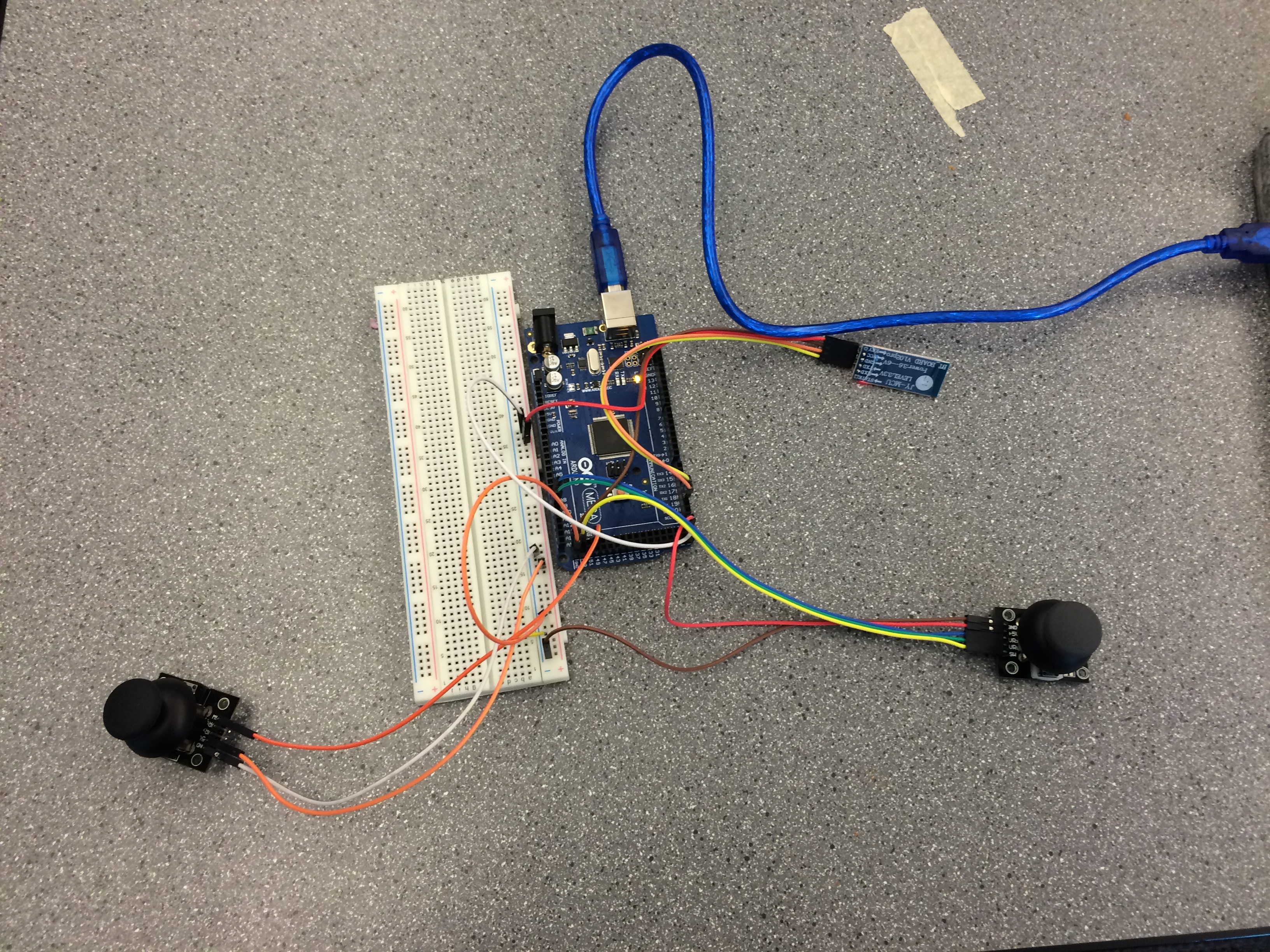
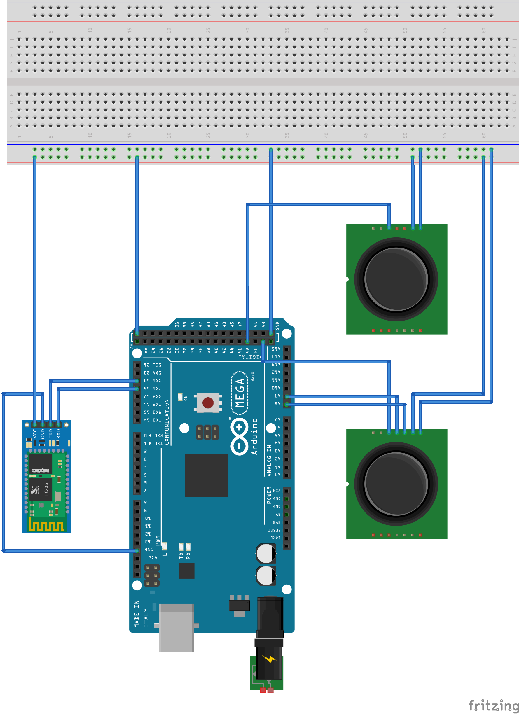
Base Station Wiring Diagram
One of the joysticks only has the digital pushbutton pin connected.
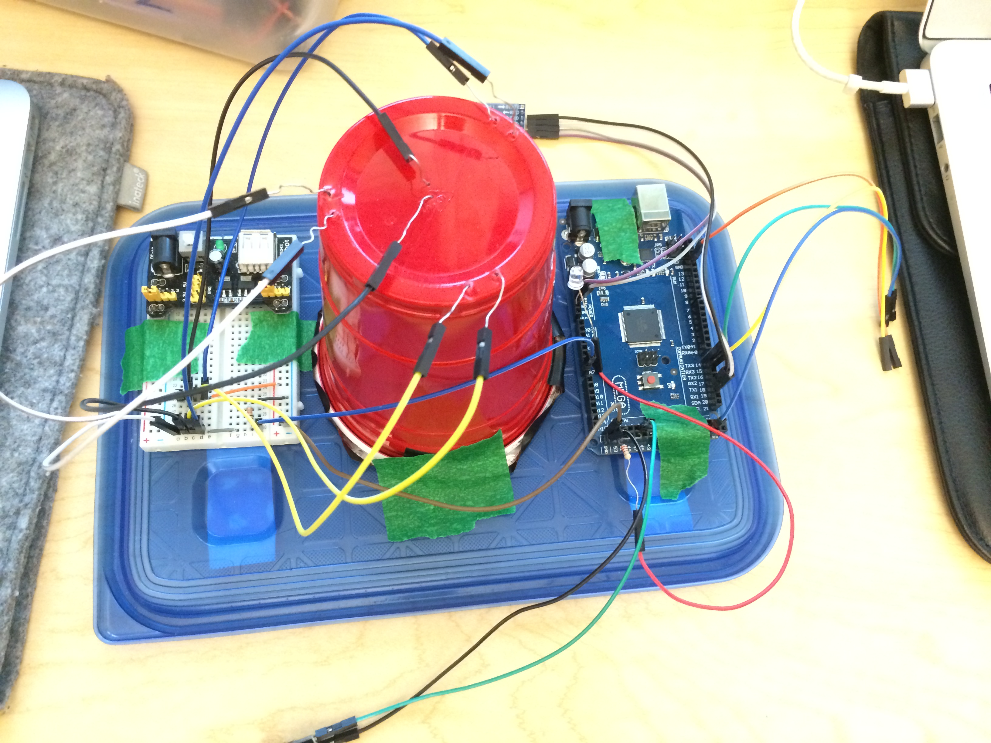
Remote Station Wiring Diagram
The four wires left unplugged are for attaching to the Roomba.
Base Station
Remote Station
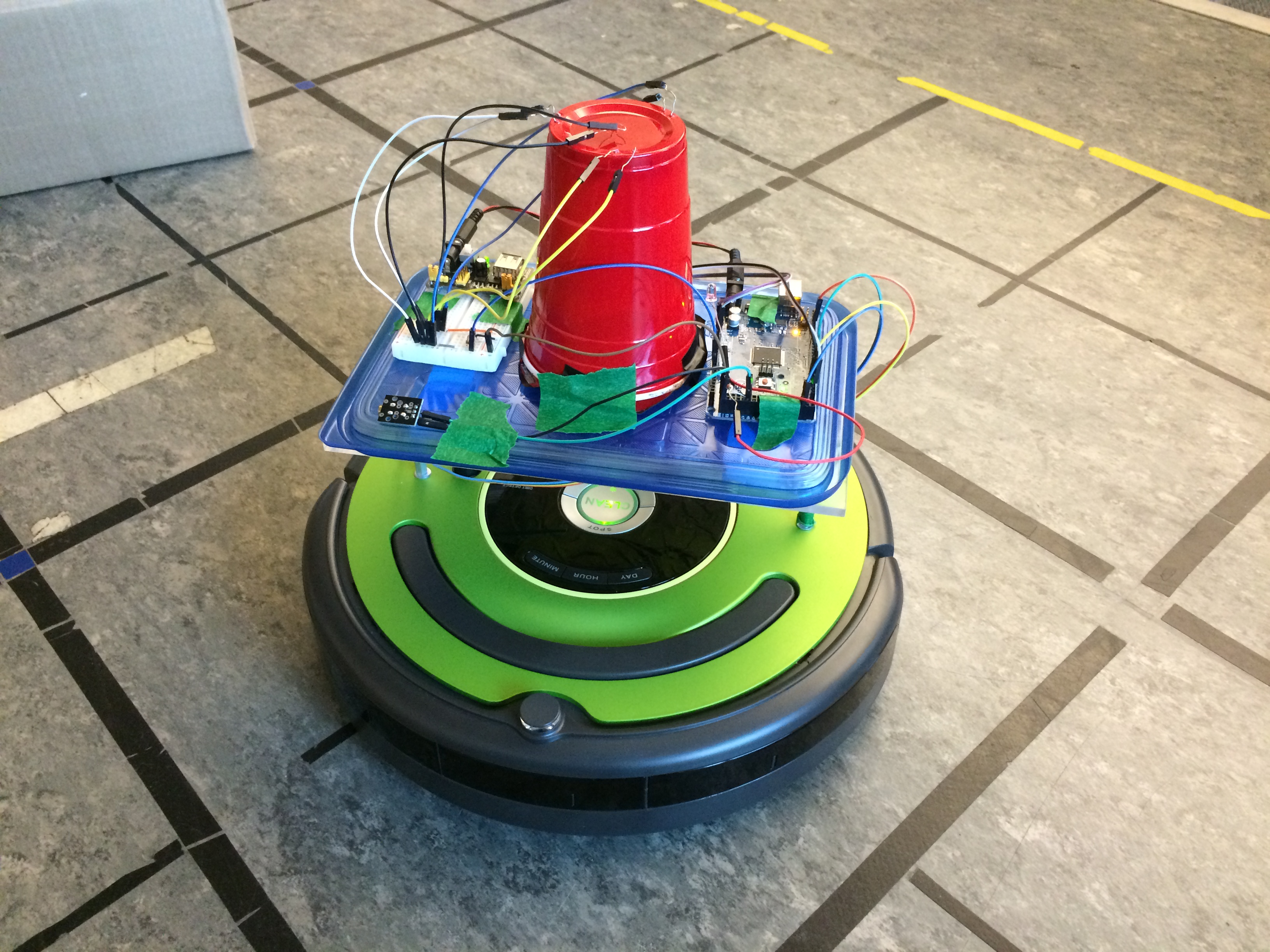
Remote Station Mounted
Code
The code API as generated by Doxygen is available here.
You can download the project 3 source code here.
