
Project 2
Contents
Introduction
The goal of project 2 is to implement, and test a priority based, preemptive, multithreaded real time operating system (RTOS). This is done on the same microcontroller as in project 1, the ATMega 2560. The RTOS will have similar features to the pthread library including mutexes and priority inheritence.
Hardware
Arduino ATMega 2560
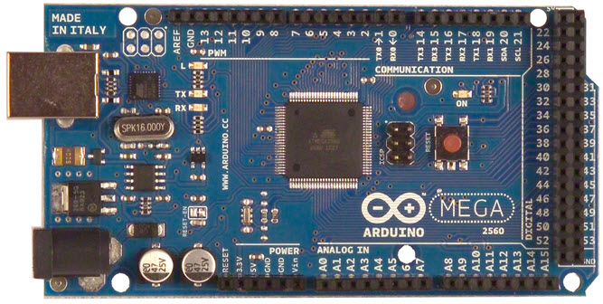
The ATMega 2560 is an Atmel 8-bit AVR RISC based microcontroller with 256 KB of flash memory and 8 KB of SDRAM running at 16MHz.
17-Bit Address Problem
AVR architectures store instructions in the flash part of memory. This memory is normally accessed by 2 byte words that are addressed with 16 bit addresses. This means the maximum amount of memory that can be addressed by 16 bits is 2*2^16 bytes, or 128 KB. Since the ATMega has 256 KB of flash, it uses extended addressing to address the upper part of memory. This means the CPU effectively uses a 17 bit address, with an extra bit stored in the EIND (extended indirect) register. The compiler then calls functions in memory using special instructions (like eijmp and eicall), that concatenate the EIND register with the 16 bit Z (r30 and r31) register that stores the the first 16 bits of the address. In order to fix the 17-bit address problem in the RTOS, the RTOS needs to store the EIND register when it saves a task's context, and restore the EIND register when it restores a task's context. Also when the workspace for a task is initialized, there needs to be a 3 byte (instead of a 2 byte) return address for the program counter. Context switching will be illustrated later, but these two fixes are shown below:
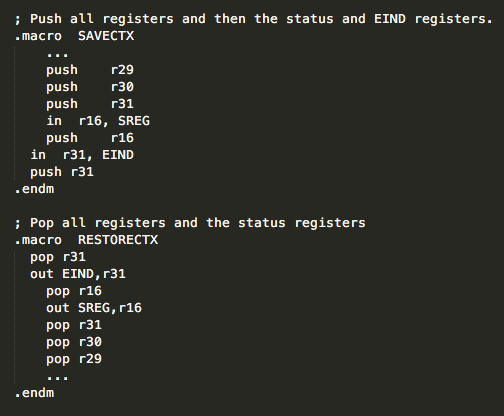

As you can see, the third byte is set to 0 when the task is initialized.
RTOS Design
Booting, Context Switching, and the Kernel
RTOS BootingWhen the RTOS boots, it makes a one-time call to OS_Init, which initializes the required memory for MAXTHREAD number of tasks, MAXMUTEX number of mutexes, and MAXEVENT number of events. The state of these 3 types of resources are all set to an inactive or dead state. The RTOS then creates a task called a_main. a_main is an application level function with the highest priority. It will run after the RTOS has finished booting and create any necessary tasks, mutexes, and events through system calls to the running RTOS. OS_Start is then called to change the state of the kernel to active. The kernel can then begin running by scheduling and dispatching the a_main task created earlier.
Timers and InterruptsTwo of the 16-bit PWM timers (Timer1 and Timer3) on the ATMega 2560 were used to control the flow of the RTOS. Both were configured in CTC (Clear Timer on Compare) mode with TOP values to control the rate at which their relative timer compare-vectors were set. Interrupt handlers were then created for the periodic interrupts that occurred. Timer1 fires an interrupt every 10 ms. Its corresponding Interrupt Service Routine (ISR) checks the SleepQueue to see if any task has finished sleeping and if so will move it back to the ReadyQueue. It also calls Task_Next so that tasks with the same priority are cooperatively sharing the CPU. Timer 3 is used as a real time clock to keep track of the amount of time that has passed since the RTOS booted. Timer3 fires an interrupt every second and increments a global overflow count. This timer is used to put tasks to sleep and wake them up using absolute time as discussed later in the Task Sleep section.
The KernelThe kernel of the RTOS is itself a pseudo-task in that its context is saved to and restored from RAM in the same way as all of the processes. Its entire function body boils down to a switch statement that is invoked based on the current process's request to the kernel. This switch statement can be thought of as a way for the application to make system calls for the kernel to execute. Most of the kernel's switch statements call kernel-level functions that contain the actual implementation of task, mutex, and event actions. These functions are inaccessible to the application that is utilizing the RTOS, which gives the system a security buffer, in that the RTOS code itself cannot be compromised by a regular user. Any system call (request) to the kernel will disable interrupts. Interrupts will then remain disabled until the kernel exits.
A list of all kernel requests are given here:
- NONE
- CREATE
- NEXT
- SLEEP
- TERMINATE
- SUSPEND
- RESUME
- MUTEX_INIT
- MUTEX_LOCK
- MUTEX_UNLOCK
- EVENT_INIT
- EVENT_WAIT
- EVENT_SIGNAL
Priority Scheduling
All active tasks have a priority from 0 (highest) to 10 (lowest). The task with the highest priority will be the task that runs next. If there are tasks with equal priority, they will execute cooperatively on a first-come-first-served basis.
DispatchThe Dispatch function is the scheduler. Every time dispatch is called, it takes the highest priority task from the ReadyQueue and sets it to become the next running task. The scheduler always picks a task whose state is READY, and who is not suspended.
Tasks
OverviewThreads are represented by "tasks". Each task is represented by a process descriptor struct, which contains all location and state information about each task. In addition, each process descriptor contains a memory "workspace" of 256 bytes for storing the register values and return address for context-switching. Memory for MAXTHREAD number of processes is allocated upon initial booting of the RTOS. The struct has the following fields:
| PID p | The id of the task |
| unsigned char *sp | Stack pointer into the workspacee |
| PROCESS_STATES state | The state of the task |
| PRIORITY py | The original priority of the task |
| PRIORITY inheritedPy | The inherited priority (defaults to py) |
| int arg | An initial parameter given at creation time |
| voidfuncptr code | The function to be executed as a task |
| KERNEL_REQUEST_TYPE request | A request the current process can make to the kernel |
| unsigned int response | A response the kernel can give back to the calling task |
| TICK wakeTickOverflow | The overflow count that together with wakeTick can construct absolute time of the program's execution |
| TICK wakeTick | The tick count that together with wakeTickOverflow can construct absolute time of the program's execution |
| MUTEX m | The mutex the task wishes to lock |
| EVENT eWait | The event the task is waiting on |
| EVENT eSend | Used to pass data to the kernel when the task calls signal or wait |
| unsigned int suspended | Whether or not the task is suspended |
| PID pidAction | Used to pass a process id to the kernel in cases such as suspend and resume |
- DEAD
- READY
- RUNNING
- SLEEPING
- BLOCKED_ON_MUTEX
- WAITING
- TERMINATED
Task_Create is called with three parameters: the address of the function that is to run as the task, an integer value for the initial priority of the task, and an integer value for the task's initial arg. If the kernel is currently inactive, then Kernel_Create_Task will be called with these three parameters because we are already in the kernel (its booting process to be exact). Otherwise a context switch to the kernel will be initiated with the request to create a task. Upon hitting the CREATE case of the kernel, Kernel_Create_Task will immediately be called, which (if the MAXTHREAD hasn't been exceeded) locates an available DEAD process spot in the Process array that the new task can occupy. On finding this spot, Kernel_Create_Task_At is called with the original three parameters as well as the newly discovered free Process address. Kernel_Create_Task_At clears the contents of the new process' workspace, and inserts the address of the Task_Terminate function at the bottom of the stack (in case the task returns, so the process slot can be freed). Above this, it inserts the return address of the function, and then skips the stack-pointer ahead 34 bytes. The stack pointer needs to be moved ahead because when this task executes for the first time, the context switching code will attempt to pop registers 0 - 31, SREG, and EIND, so initial dummy values need to be in place. Finally, the process descriptor variables are initialized, the task is set to READY, and it is enqueued in the ReadyQueue.
Task_NextTask_Next sets the kernel request to NEXT and enters the kernel. The kernel simply sets the state of the current process to READY, enqueues the current process into the ReadyQueue, and calls Dispatch.
Task_GetArgCalling Task_GetArg will return the initial "arg" parameter that was given to a task at creation time.
Task_SuspendTask_Suspend takes the process id to be suspended and assigns it to the current processes's pidAction variable. After also setting the process's kernel request to SUSPEND, it context-switches to the kernel, where it hits the SUSPEND case of the switch statement. From this case, Kernel_Suspend_Task is called, which either sets the "suspended" flag of the current process to 1 (if it is the current process that is to be suspended), or locates the target process using the pidAction variable and sets its suspended flag to 1. Upon returning to the kernel switch case, Dispatch is called if it was indeed the current process that was suspended. It is important to note that suspended tasks can changes states, can be woken up and moved to the ReadyQueue, can acquire mutexes if they were blocked on a mutex, but cannot become running until they are resumed.
Task_ResumeTask_Resume also takes in a process id to be resumed. It looks up the process to be resumed, and sets its suspended flag to 0. If the resumed task has a higher priority then the running task, Dispatch is called to pre-empt it.
Task_SleepCalling Task_Sleep will add the TICKS parameter you pass to it to the current count of Timer 3 (converted to TICKS), counting any overflow (above 100 TICKS) in a special variable. It then enters the kernel with the TICKS and overflow set to when the task should be "woken up". The kernel simply enqueues the task into the SleepQueue and calls Dispatch.
Task_TerminateA task can terminate itself by calling Task_Terminate. Termination is immediate, so the first action is to raise the priority of the terminating task to 0 (highest), and set the state to TERMINATED. Now all mutexes locked by this process can be released or given away if another task is waiting for them, then the state of the task is set to DEAD. Since tasks can only terminate themselves, there is no need to check any queues because the task is running.
Mutexes and Priority Inheritence
OverviewA mutex is a resource that acts like a binary semaphore which tasks can lock and unlock. A mutex has 3 properties of ownership, recursiveness, and inheritence. All mutexes are stores in an array called Mutexes, and respresented by a struct with the fields: m (id), state, owner, and lockCount. A mutex has 3 states: DISABLED, FREE, and LOCKED.
Mutex_InitWhen a mutex is initialized, the lockCount is set to 0, the state is set to FREE, the id is set to a number from 0 - 15, and the owner is set to NULL.
Mutex_LockWhen a task calls Mutex_Lock(m), if the mutex is free, then the state is set to LOCKED, the lockCount is set to 1, and the owner is set to the calling tasks id. If the mutex is locked, and the calling task is the owner, then the lockCount is incremented as mutexes allow recursive locks. This does mean it must be unlocked the right number of times to become free. And if the mutex is locked and the calling task is not the owner, its state becomes BLOCKED_ON_MUTEX and it enters the WaitingQueue. When this happens, if the task that became blocked has a higher priority then the task with the mutex, the task with the mutex inherits the higher priority for the duration that it holds the mutex. This is a solution to the priority inversion problem where the high priority task could be pre-empted by a medium priority task. The WaitingQueue functions as a first-come-first-served queue.
Mutex_UnlockWhen a task calls Mutex_Unlock(m), If the lockCount is greater than 1, then it is decremented by one. If the lockCount is 1, and nobody is waiting on it, then the state it set to FREE, the owner is set to NULL, and the lockCount is set to 0. If the lockCount is 1, and there is a task waiting on the mutex, then in order to prevent barging, the lockCount will stay at 1, the state will stay locked, but ownership will be transferred to the task that is blocked on that mutex (and put back into the ready queue). The priority of the unlocking task will also be set back down to its original priority if it had inherited a higher priority. A task that is currently terminating may wish to unlock its mutexes, and if the state of the unlocking task is TERMINATED, all mutexes will be immediately unlocked, or have ownership transferred with lockCounts being set back to 1.
Events
OverviewAn event is a resource that tasks can wait on and signal. An event has 3 states: INACTIVE, UNSIGNALLED, and SIGNALLED. Only one task can wait on an event at a time. An event is represented by a struct with the fields state, e (id) and p (for the process that is waiting on the event if any). The structs are all stored in an array called Events.
Event_InitWhen initialized, the state it set to UNSIGNALLED, the id e is set to a number from 0 - 15, and p is set to NULL.
Event_WaitWhen a task calls Event_Wait(e), the task will be blocked if nothing else is waiting on the event and if the event has not yet been signalled (The task's state will be changed to WAITING). If the event has already been signalled, then the event's state will be set back to UNSIGNALLED and the calling task will continue to execute. Tasks that are in the WAITING state are enqueued back into the ReadyQueue but will never be dispatched until their state is set back to READY. If a different task is already waiting on the event, then the calling task will continue to execute.
Event_SignalAny running task can signal an event. If a task is waiting on that event, the waiting task's state is set back to READY and the event's state goes back to UNSIGNALLED. If no task is waiting on the event, then the state of the event is simply set to SIGNALLED as events record one signal and drop any subsequent signals.
Error Handling
Recoverable ErrorsThe RTOS can recover from a number of errors. These errors and the RTOS behavior are described in the following table:
| Creating one more task than MAXTHREAD | The task is not created and RTOS continues on (no-op) |
| Initializing one more mutex than MAXMUTEX | The mutex is not created and RTOS continues on (no-op) |
| Locking or unlocking a mutex that does not exist | No mutex is locked and the RTOS continues on |
| Suspending or resuming a task that does not exist | No task is suspended or resumed and the RTOS continues on |
Some errors can occur that will require the RTOS to be rebooted. These include:
| Deadlock | If two tasks get into a deadlock due to the application designer's coding, the system must be restarted |
Testing
RTOS testing was conducted using a USB logic analyzer. Testing was split into 6 distinct categories. These cateogories are the initial tests provided by Daniel, Task Termination, Suspension and Resumption, Sleeping, Mutexes and Priority Inheritence, and Events. Each category has multiple tests that attempt to isolate a specific piece of functionality. The tests provide good coverage of all the features implemented and give us reliability in our RTOS.
Initial Tests
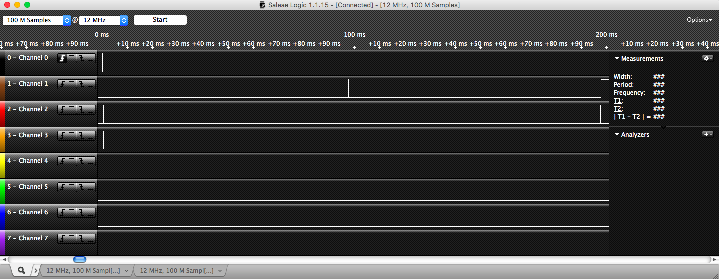
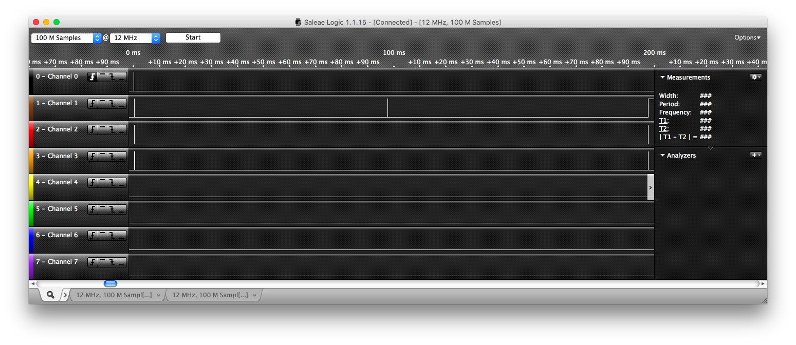
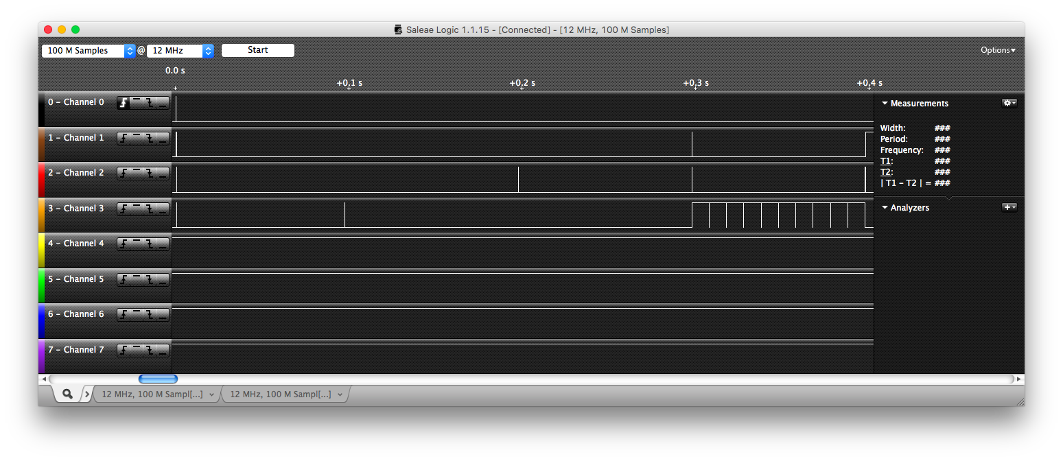
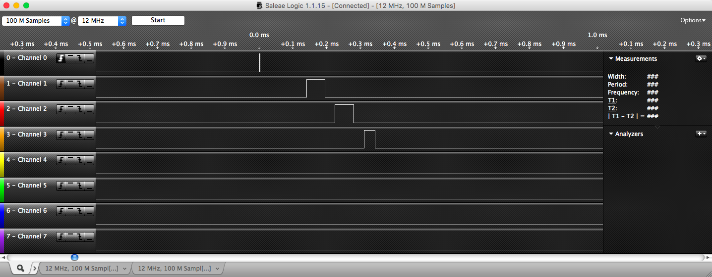
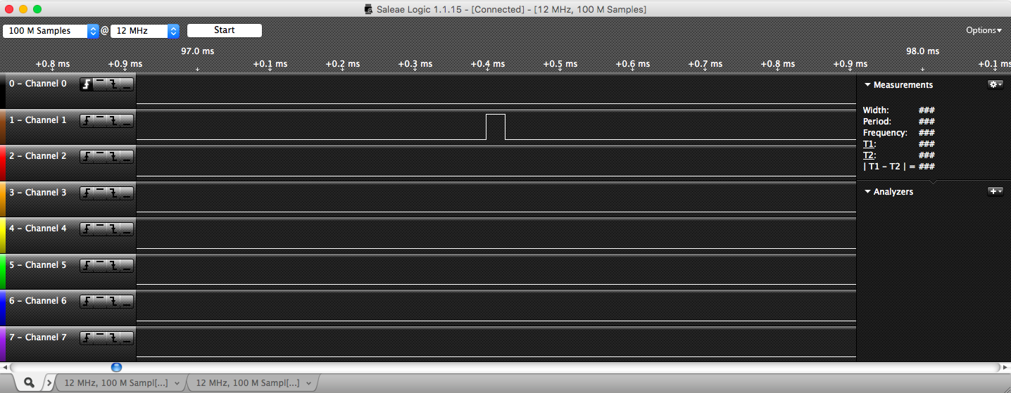
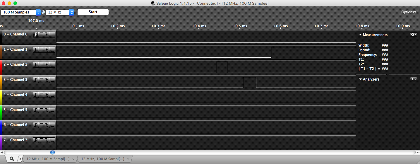
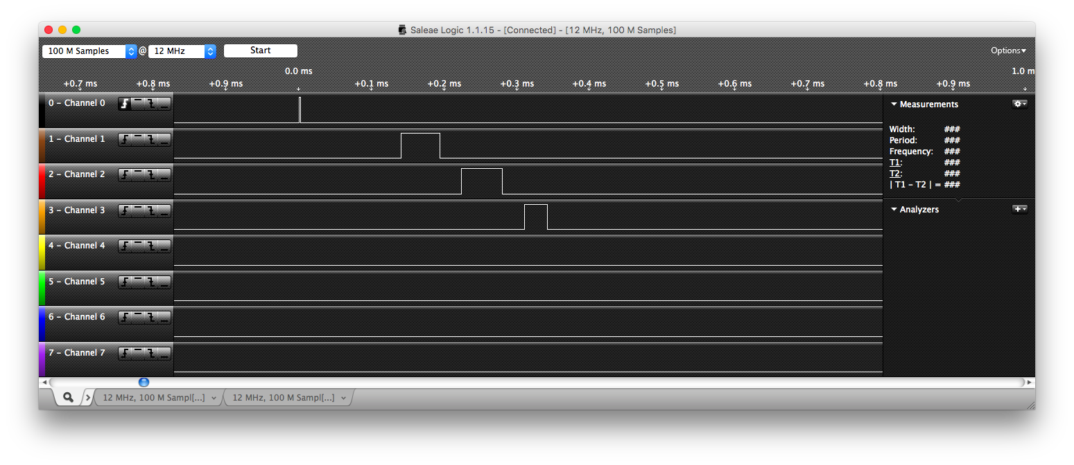
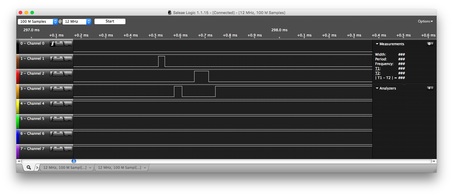
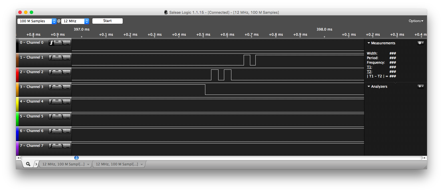
Please note that for tests 1-3: Channel 0 is used as the trigger, and Channel 1 corresponds to P1, Channel 2 to P2, and channel 3 to P3.
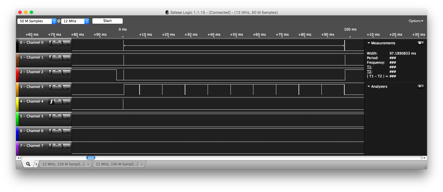
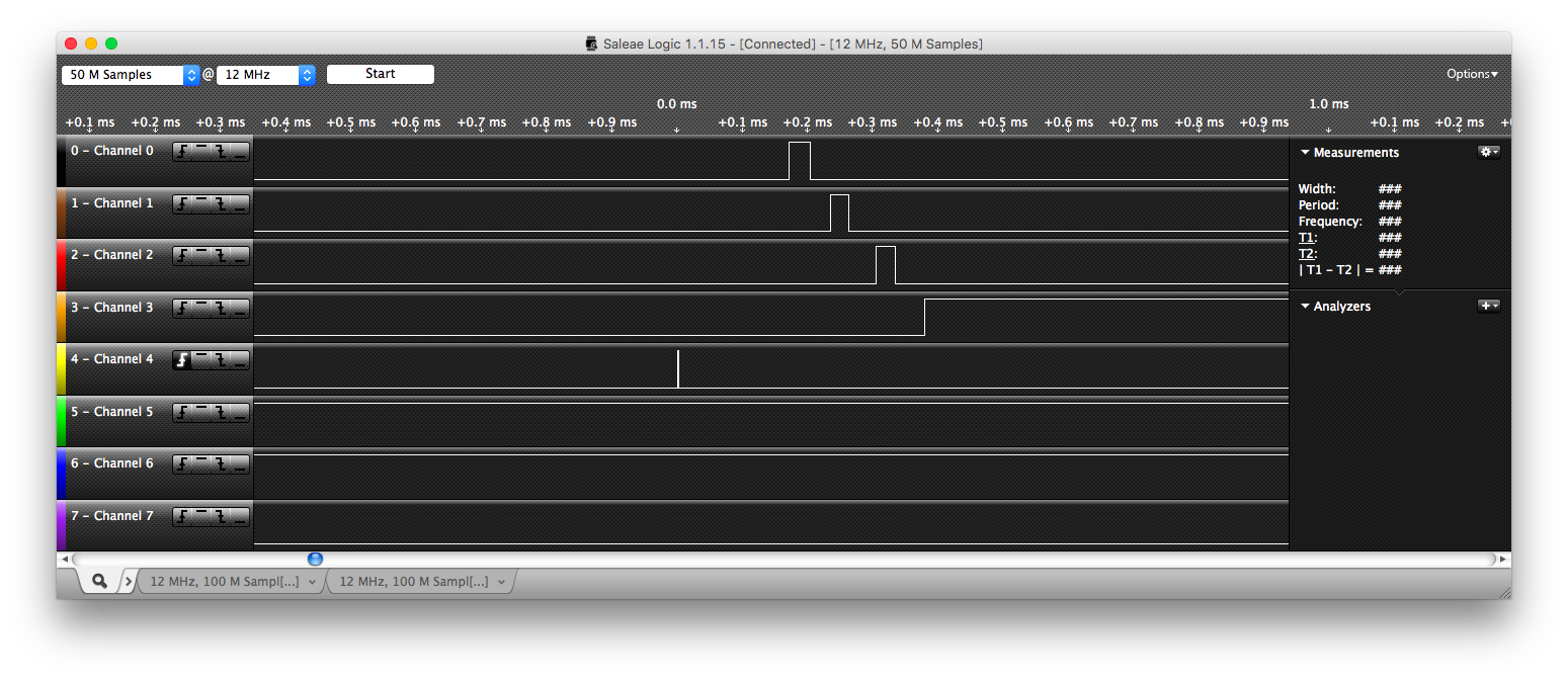
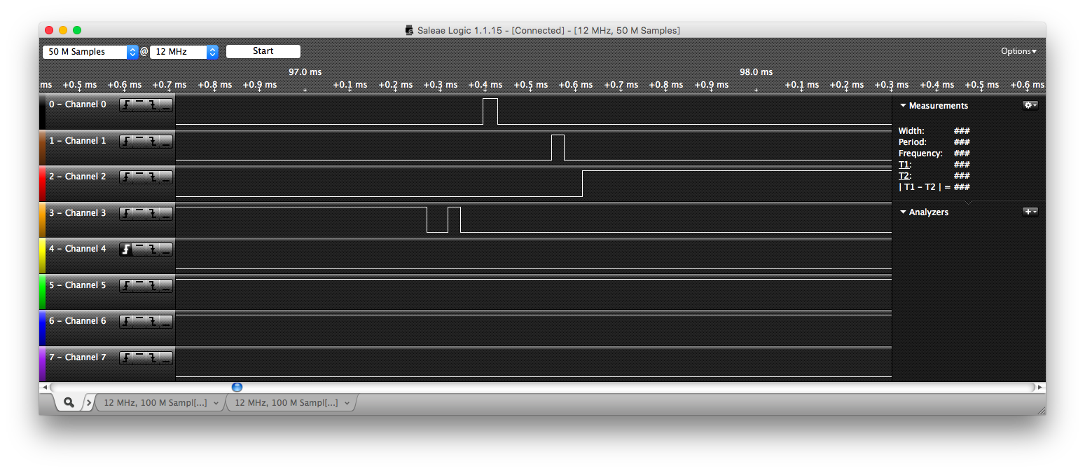
And for test 4: Channel 0 corresponds to P0, Channel 1 to P1, Channel 2 to P2, Channel 3 to P3, and Channel 4 to the trigger.
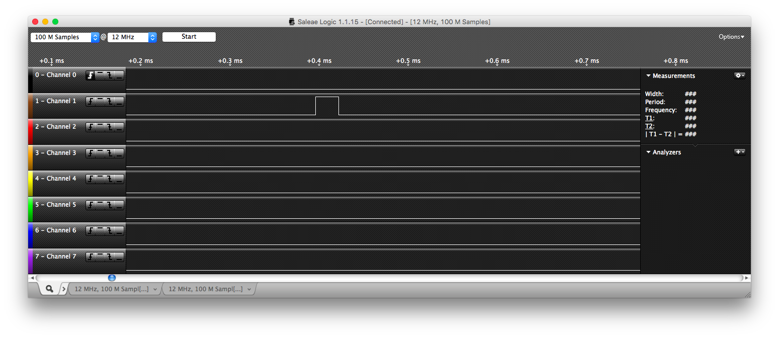
| Objective: | Test 1 was provided by Daniel and has an expected running order of: P1, P2, P3, P1, P2, P3, P1. This task tests mutexes, events, sleeping, and priority inheritence. |
| Description: | Tasks P1, P2, and P3 are created with priorities 1, 2, and 3 respectively. P1 sleeps, P2 sleeps, P3 locks a mutex and waits on an event. P1 attempts to lock the mutex but is blocked, boosting P3's priority, P2 signals the event, P3 resumes and unlocks the mutex (transferring ownership to P1) and lowering its priority back to normal, P1 pre-empts P3. |
| Results: | As shown in the screen capture below, our results are consistent with the expected running order of P1, P2, P3, P1, P2, P3, P1. For zoomed in screenshots please refer to the appendix. |
 Test 2
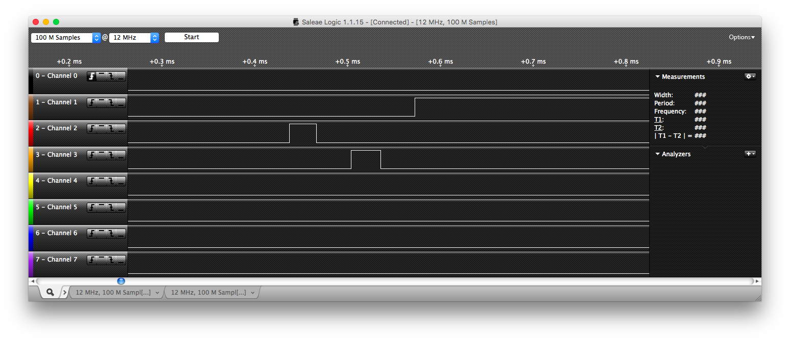
| Objective: | Test 2 was provided by Daniel and has an expected running order of: P1, P2, P3, P1, P2, P3, P1. This task tests mutexes, sleeping, and suspension and resumption. |
| Description: | Tasks P1, P2, and P3 are created with priorities 1, 2, and 3 respectively. P1 sleeps, P2 sleeps, P3 locks a mutex and suspends itself, P1 attempts to lock the mutex but becomes blocked and boosts P3's priority, P2 resumes P3, P3 unlocks the mutex (and transfers ownership to P1), lowering its priority back to normal and is pre-empted by P1. |
| Results: | As shown in the screen capture below, our results are consistent with the expected running order of P1, P2, P3, P1, P2, P3, P1. For zoomed in screenshots please refer to the appendix. |
 Test 3
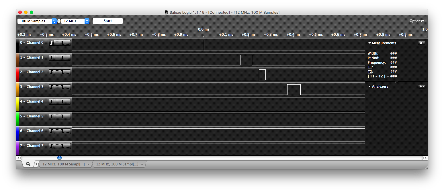
| Objective: | Test 3 was provided by Daniel and has an expected running order of: P1, P2, P3, P3, P2, P1, P3, P2, P3, P2, P1. This test performs an in-depth test on mutexes and priority inheritence. |
| Description: | Tasks P1, P2, and P3 are created with priorities 1, 2, and 3 respectively. P1 sleeps, P2 locks mutex 1 and sleeps, P3 sleeps, P3 wake ups and locks mutex 2 and sleeps, P2 wakes up and tries to lock mutex 2 but is blocked, which boosts P3's priority. P1 wakes up and tries to lock mutex 1 but is blocked and boosts P2's priority, P3 wakes up and unlocks mutex 2 (transferring ownership to P2) and lowering its priority back to normal, P2 pre-empts P3 and then sleeps, P3 being the only available task runs until P2 wakes up again, P2 unlocks both mutexes (transferring ownership of mutex 1 to P1) and lowering its priority back to normal, and allows P1 to run. |
| Results: | As shown in the screen capture below, our results are consistent with the expected running order of P1, P2, P3, P3, P2, P1, P3, P2, P3, P2, P1. For zoomed in screenshots please refer to the appendix. |
 Test 4
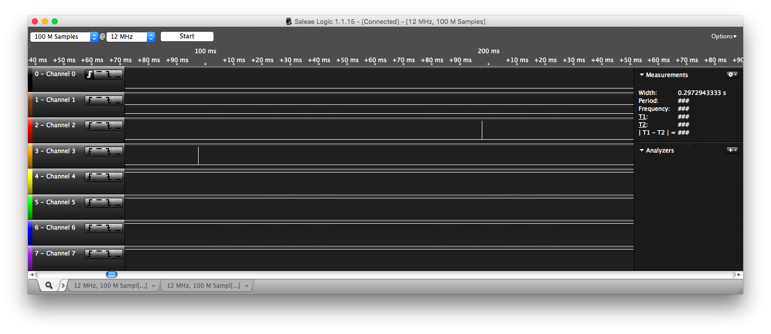
| Objective: | Test 4 was provided by Daniel and has an expected running order of: P0, P1, P2, P3, TIMER, P0, P1, P2. This task tests event waits and using a timer interrupt to send a signal. |
| Description: | Tasks P0, P1, P2, and P3 are created with priorities 0, 1, 2, and 3 respectively. P0 waits on evt3, P1 waits on waits on evt1, P2 waits on evt2, and P3 being the only ready task becomes running. After 0.1 second, Timer3 triggers an interrupt to signal evt1, which wakes up P0, P0 then signals evt2 and evt1 and then waits on evt3 again, which allows P1 to run and P1 in turn waits on evt1 again, allowing P2 to run forever. |
| Results: | As shown in the screen capture below, our results are consistent with the expected running order of P0, P1, P2, P3, TIMER, P0, P1, P2. For zoomed in screenshots please refer to the appendix. |
Task Termination
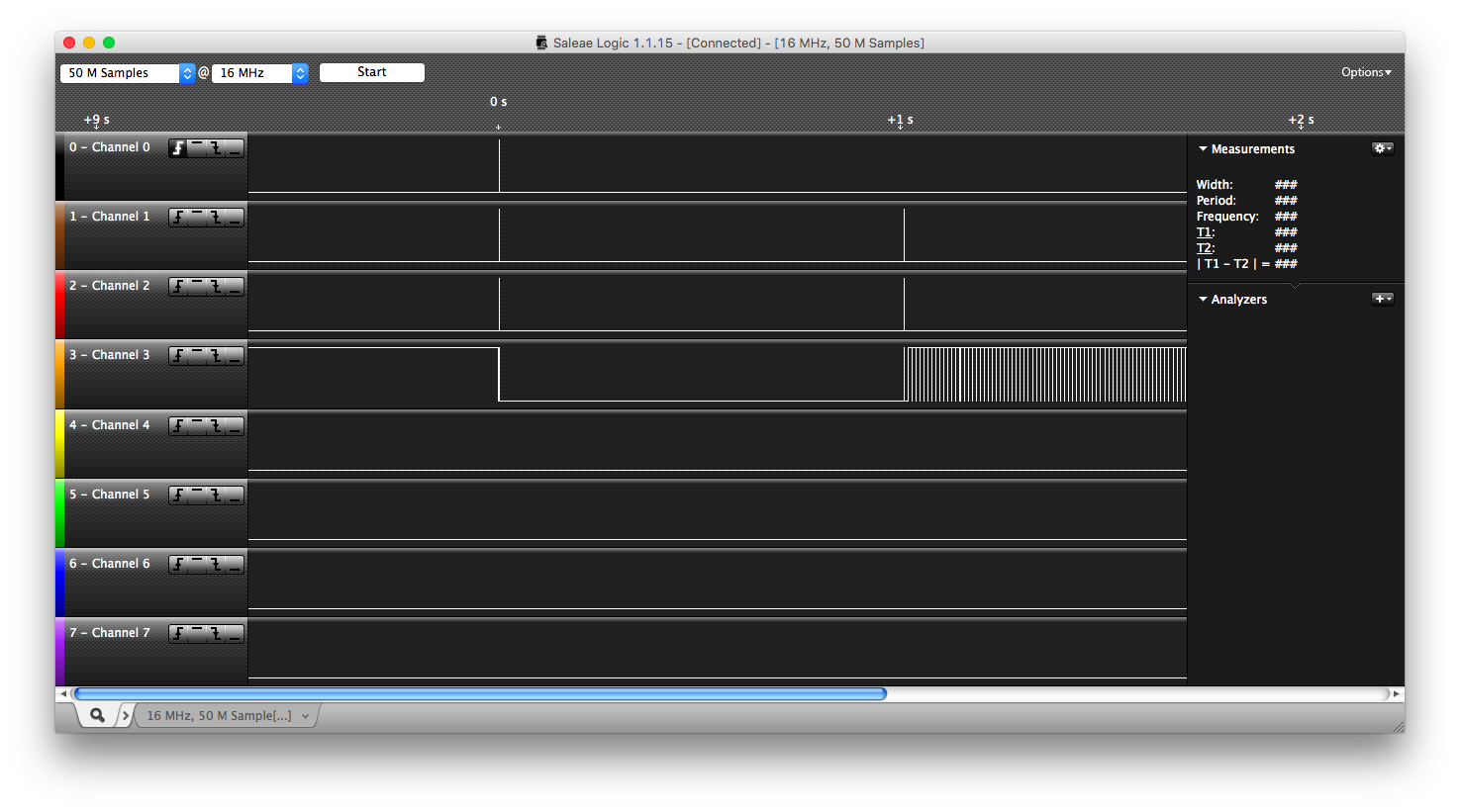
Test 1 has Channel 0 as the trigger, Channel 1 as P1, Channel 2 as P2, and Channel 3 as P3.
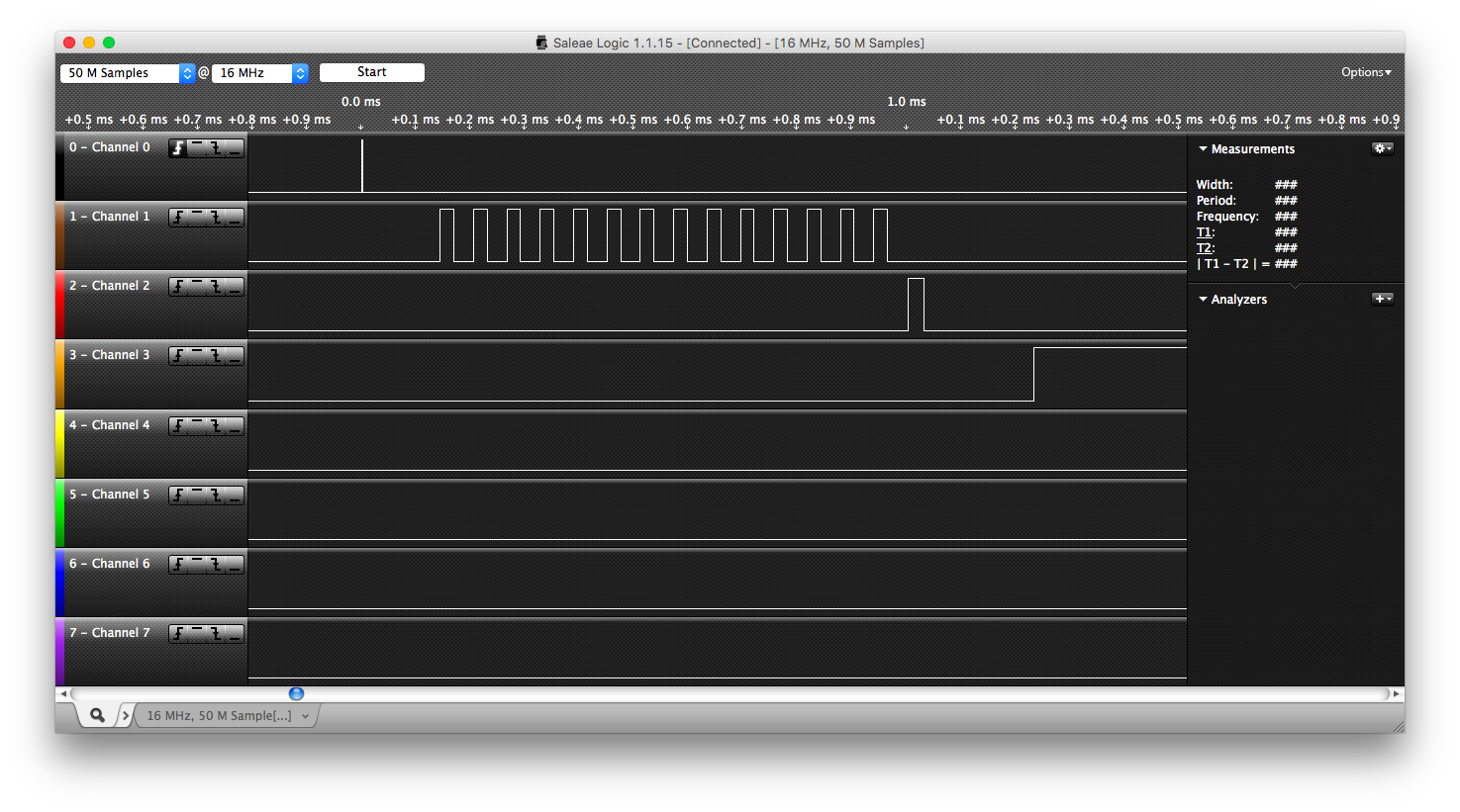
Test 2 has Channel 0 as the trigger, Channel 1 as P1 - P14, Channel 2 as P15, and Channel 3 as P16.
| Objective: | Test 1 creates 3 tasks. It tests that when a task terminates, all resources it had, including mutexes are freed (or transferred) and allowed to be used by other tasks. |
The message sequence chart is shown here:
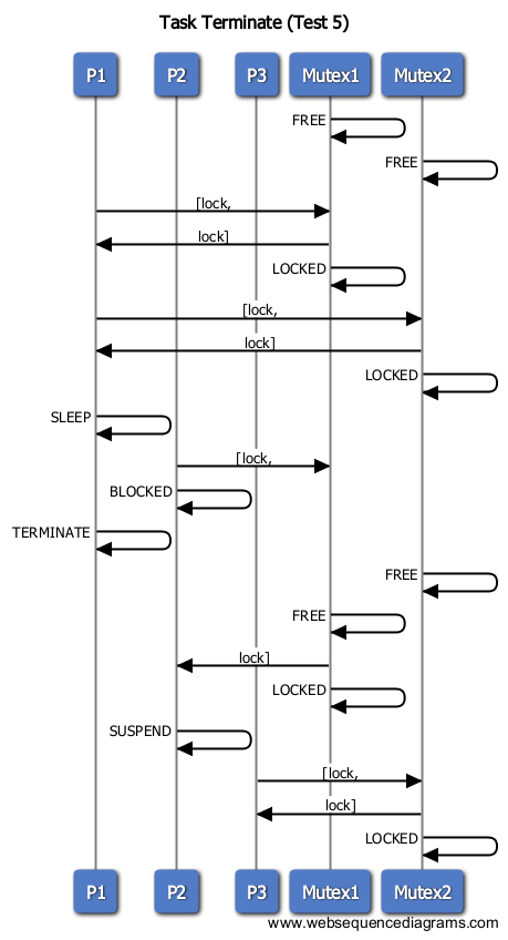
| Results: | As shown in the screen capture below, our results are consistent with the message sequence charts expected running order of P1, P2, P3, P1, P2, P3. |
 Test 2
| Objective: | Test 2 creates a_main (which is P0) which creates 15 other tasks. P0 then terminates. P1 - P14 also terminate, P15 creates P16 and then terminates, P16 runs forever. This illustrates that the RTOS can reuse dead threads by creating a total of 17 tasks. |
The message sequence chart is shown here:
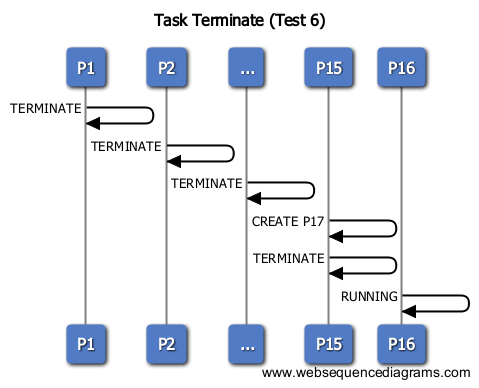
| Results: | As shown in the screen capture below, our results are consistent with the message sequence charts expected running order of P1, ..., P15, P16. |
Mutexes
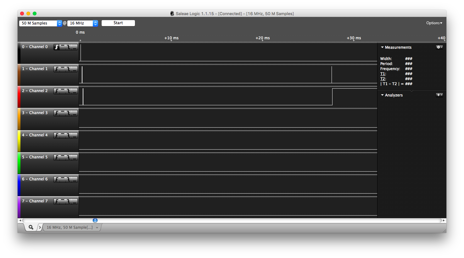
Channel 0 is the trigger, Channel 1 is P1, Channel 2 is P2, Channel 3 is P3 (if existant).
Test 1
| Objective: | This test shows the basic mutual exclusion case of a mutex. P1 locks and then sleeps in the critical section. P2 tries to lock but becomes blocked. When P1 unlocks (and transfers the lock), P2 may continue. |
The message sequence chart is shown here:
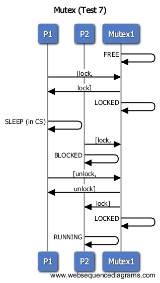
| Results: | As shown in the screen capture below, our results are consistent with the message sequence charts expected running order of P1, P2, P1, P2. |
 Test 2
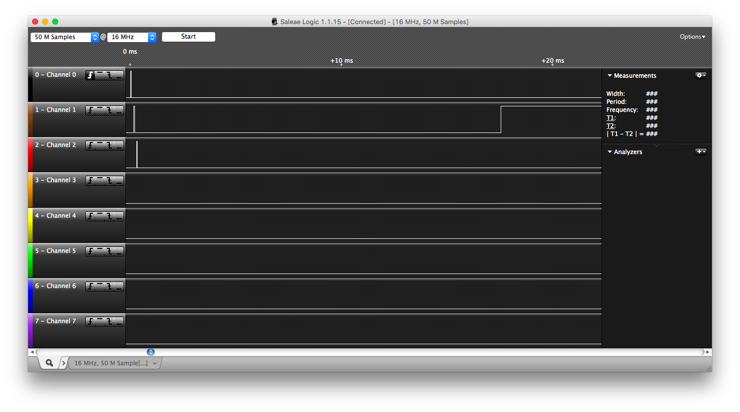
| Objective: | This test shows the ownership case of a mutex. P1 locks and then sleeps in the critical section. P2 tries to unlock the mutex, then attempts to lock. If the lock succeeds, then ownership does not hold. So P2 should be blocked and P1 should continue to run. |
The message sequence chart is shown here:
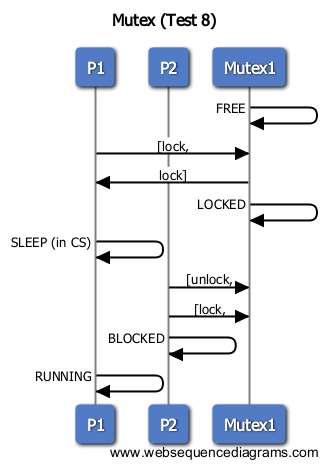
| Results: | As shown in the screen capture below, our results are consistent with the message sequence charts expected running order of P1, P2, P1. |
 Test 3
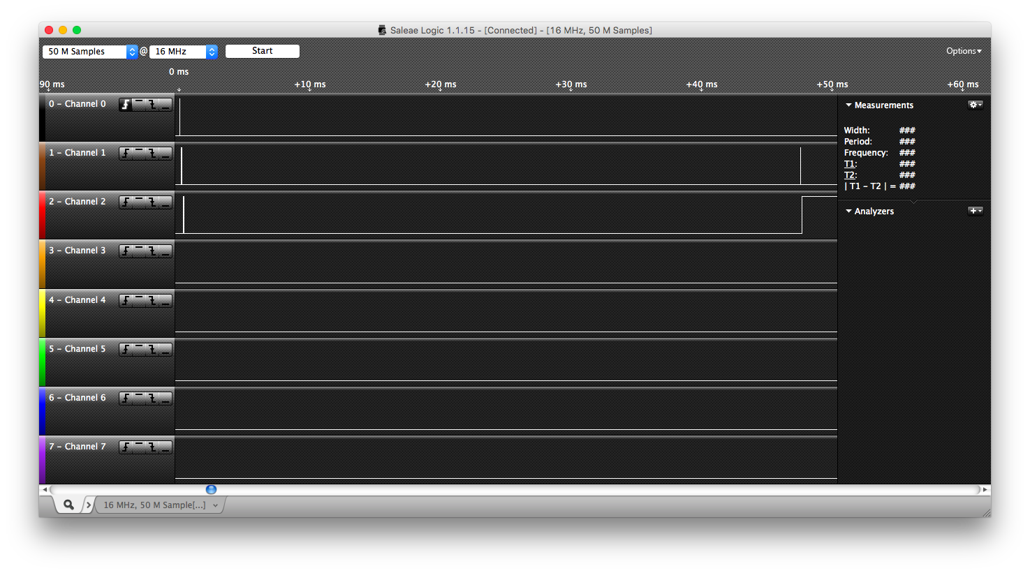
| Objective: | This test shows the recursiveness case of a mutex. P1 locks the mutex twice then sleeps, P2 attempts to lock but is blocked. P1 then must unlock twice to transfer ownership to P2 and allow it to run. |
The message sequence chart is shown here:
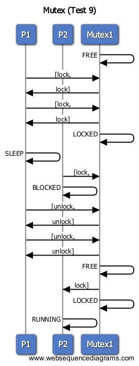
| Results: | As shown in the screen capture below, our results are consistent with the message sequence charts expected running order of P1, P2, P1, P2. |
 Test 4
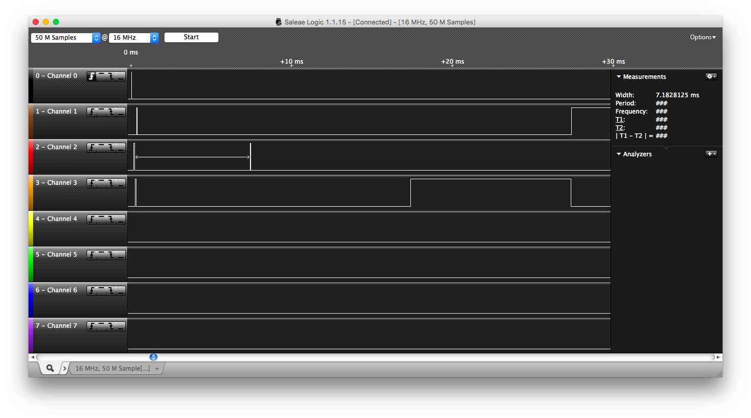
| Objective: | This case tests priority inheritence. P1 has the lowest priority, P2 has the highest, and P3 is in the middle. Tasks P2 and P3 sleep immediately, allowing P1 to lock the mutex. Then when P2 wakes up and attempts to lock the mutex, P1's priority is boosted and it is allowed to keep running. |
The message sequence chart is shown here:
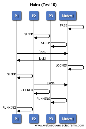
| Results: | As shown in the screen capture below, our results are consistent with the message sequence charts expected running order of P2, P3, P1, P2, P3, P1. |
 Test 5
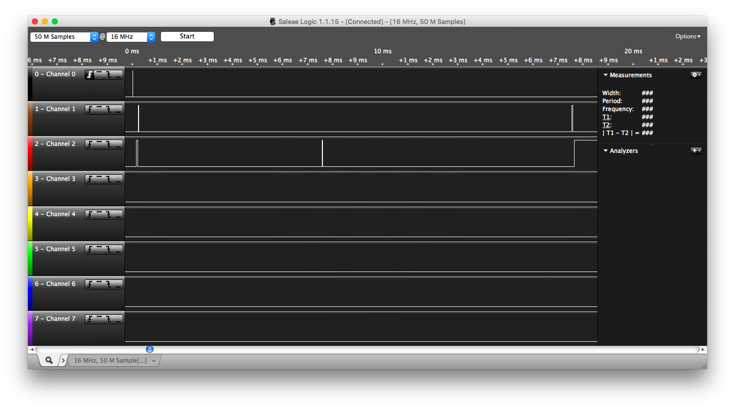
| Objective: | This case tests priority inheritence. P2 has a higher priority than P1. P2 sleeps which allows P1 to lock the mutex, then P1 sleeps, P2 attempts to lock the mutex but fails, which boosts P1's priority. Now when P1 unlocks it will be pre-empted because its priority will go back down. |
The message sequence chart is shown here:
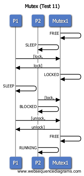
| Results: | As shown in the screen capture below, our results are consistent with the message sequence charts expected running order of P2, P1, P2, P1, P2. |
 Test 6
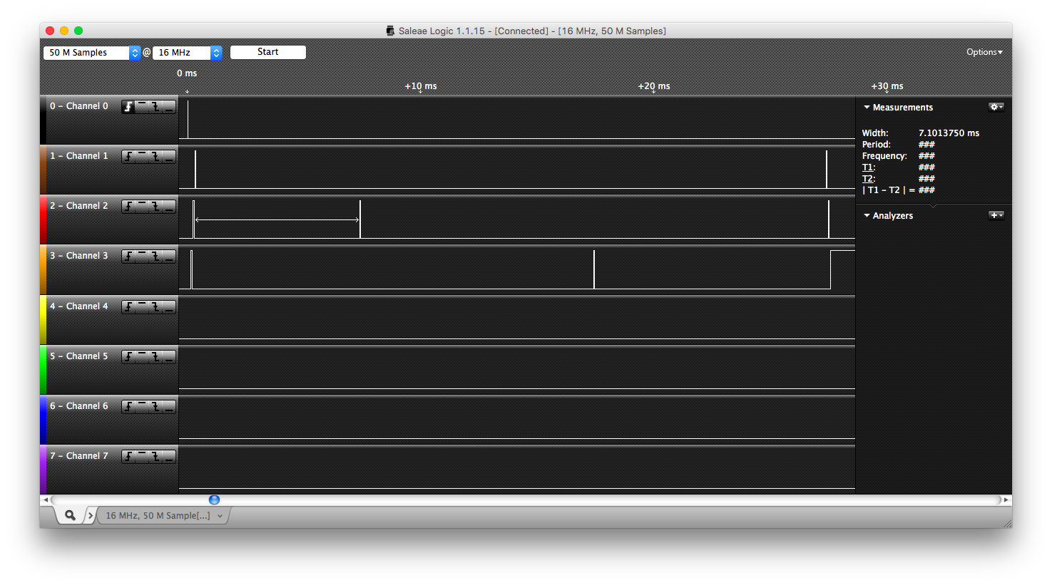
| Objective: | This case tests priority inheritence and the first-come-first-served block on mutex queue. P3 has highest priority, Then P2, then P1. The lowest priority task P1 acquires the mutex, then P2 followed by P3 both become blocked on mutex. When P1 unlocks, it should transfer the mutex to P2 due to the FIFO nature of the queue. Then when P2 unlocks, P3 gets the mutex. |
The message sequence chart is shown here:
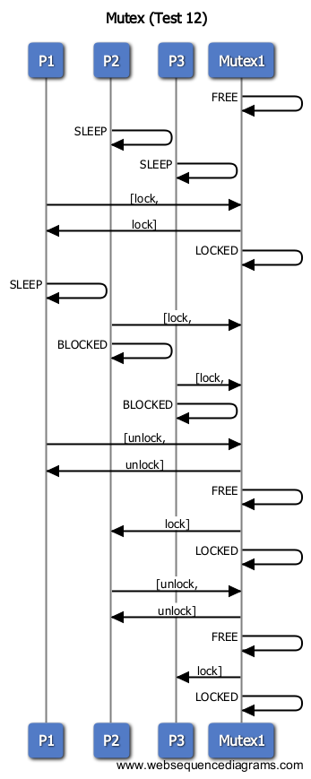
| Results: | As shown in the screen capture below, our results are consistent with the message sequence charts expected running order of P3, P2, P1, P2, P3, P1, P2, P3. |
Task Sleep
Test 1
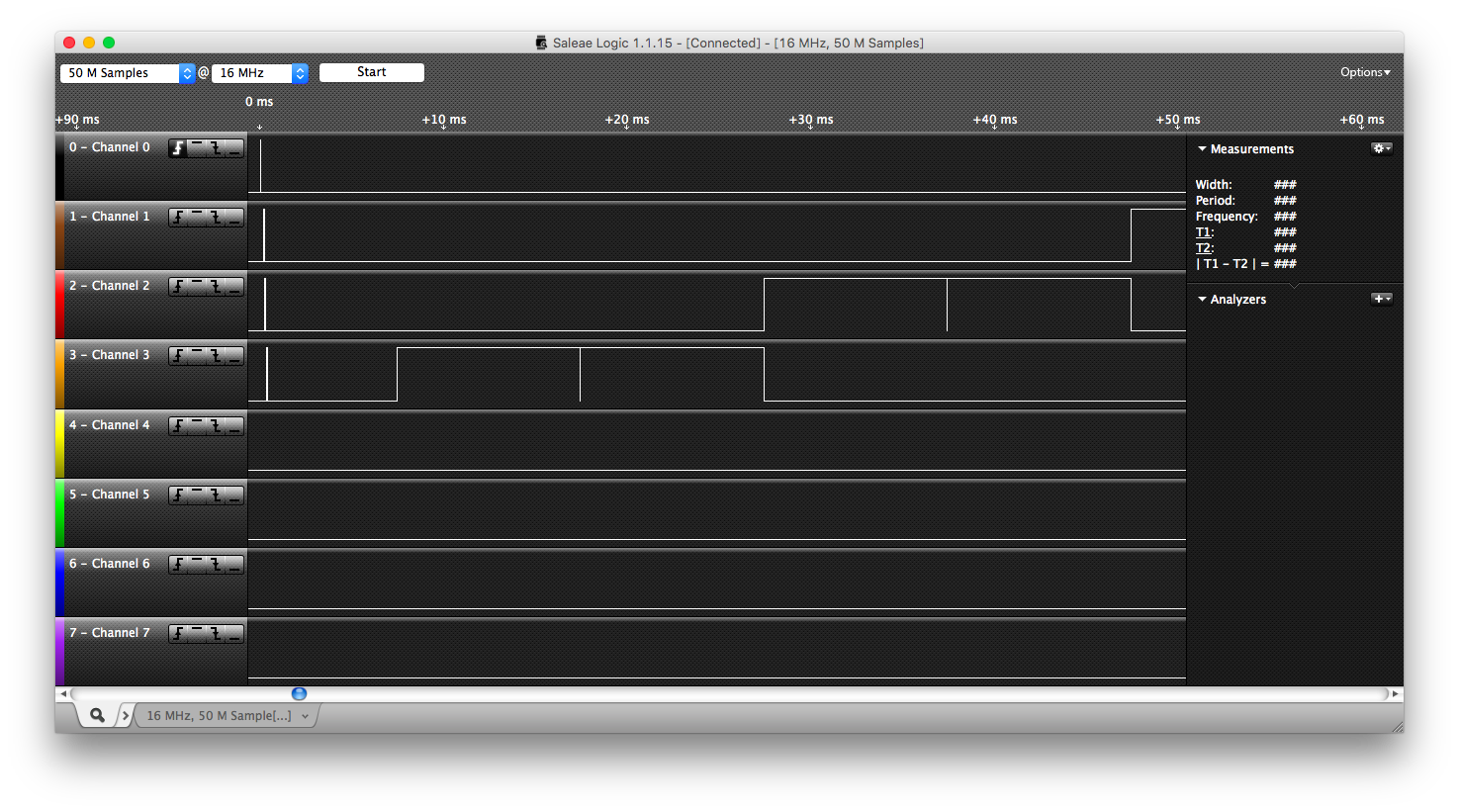
| Objective: | Test 1 creates P1, P2, and P3 with priorities 1, 2, and 3 respectively. P1 sleeps for 5 ticks, P2 sleeps for 2 ticks, P3 sleeps for 1 tick, P3 then wakes up, P2 then wakes up and pre-empts, P1 then wakes up and pre-empts |
The message sequence chart is shown here:
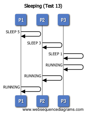
| Results: | As shown in the screen capture below, our results are consistent with the message sequence charts expected running order of P1, P2, P3, P3, P2, P1. |
Suspend & Resume
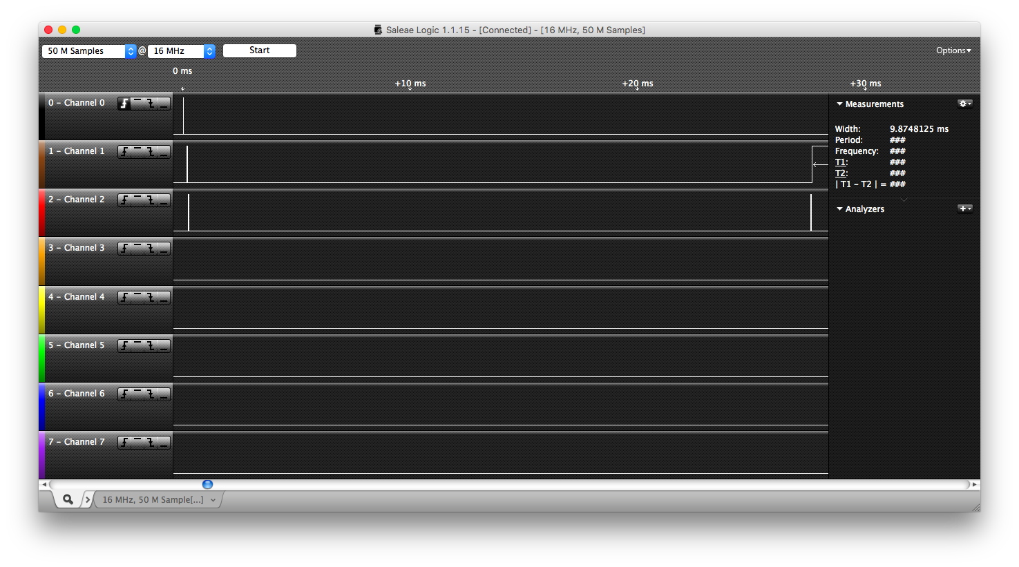
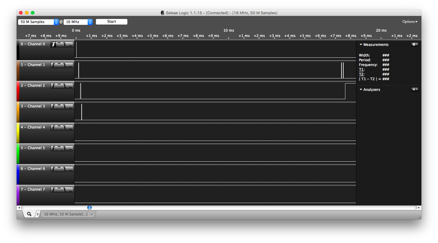
Channel 0 is the trigger, Channel 1 is P1, and Channel 2 is P2.
Test 1
| Objective: | The objective of this test is for P1 to sleep, P2 to suspend P1, then have P2 resume 1, in which case P1 will pre-empt and continue running, showing suspend and resume work. |
The message sequence chart is shown here:
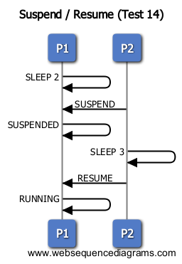
| Results: | As shown in the screen capture below, our results are consistent with the message sequence charts expected running order of P1, P2, P2, P1. |
 Test 2
| Objective: | The objective of this test is to show that even though P2 is suspended, it still receives the mutex when P1 unlocks and enters the ready state. |
The message sequence chart is shown here:
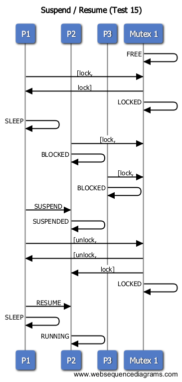
| Results: | As shown in the screen capture below, our results are consistent with the message sequence charts expected running order of P1, P2, P3, P1, P2. |
Events
Channel 0 corresponds to the trigger, Channel 1 to P1, and Channel 2 to P2
Test 1
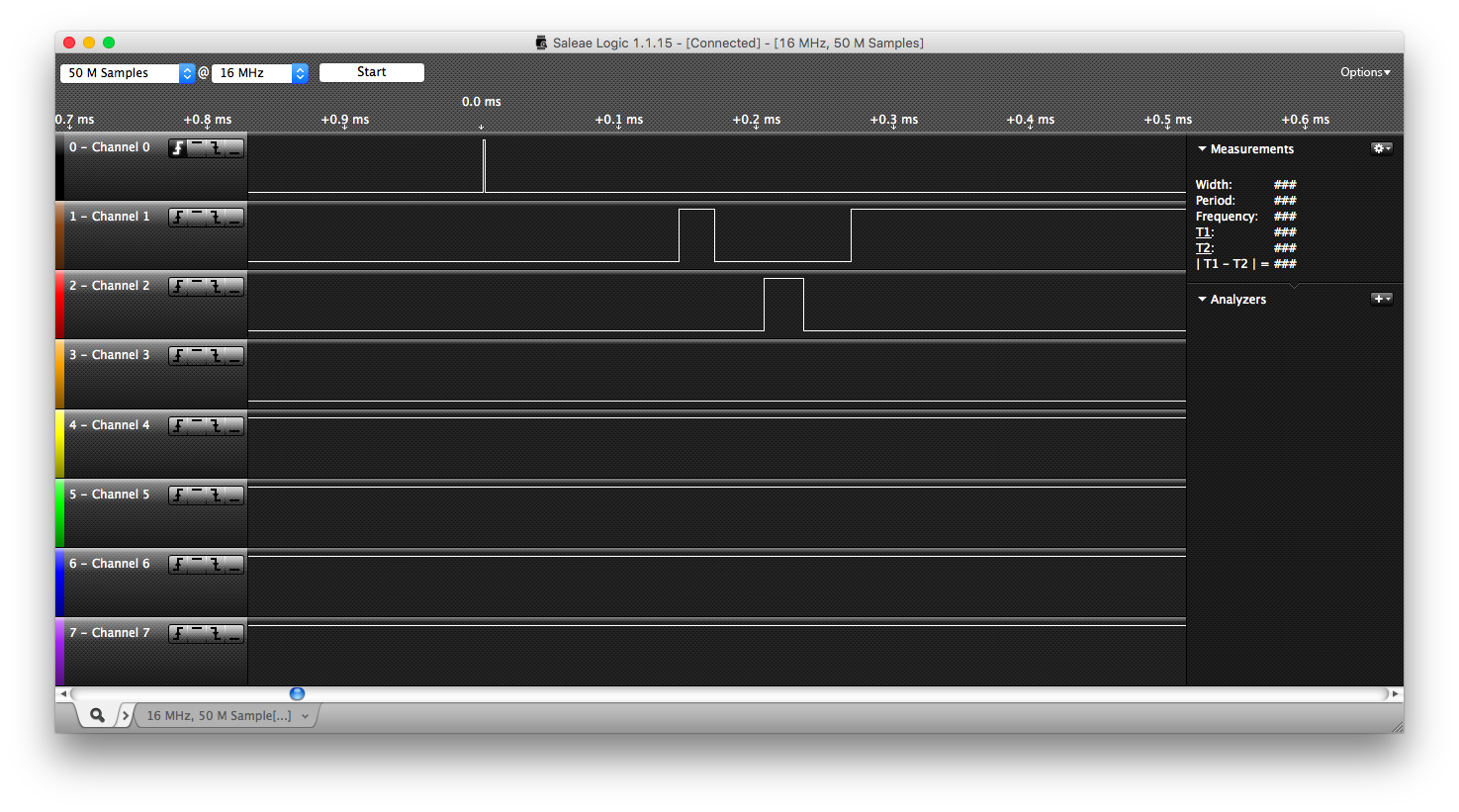
| Objective: | This test showcases the basic event wait and signal case. P1 waits on an event, P2 signals, P1 resumes. |
The message sequence chart is shown here:
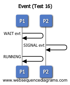
| Results: | As shown in the screen capture below, our results are consistent with the message sequence charts expected running order of P1, P2, P1. |
 Test 2
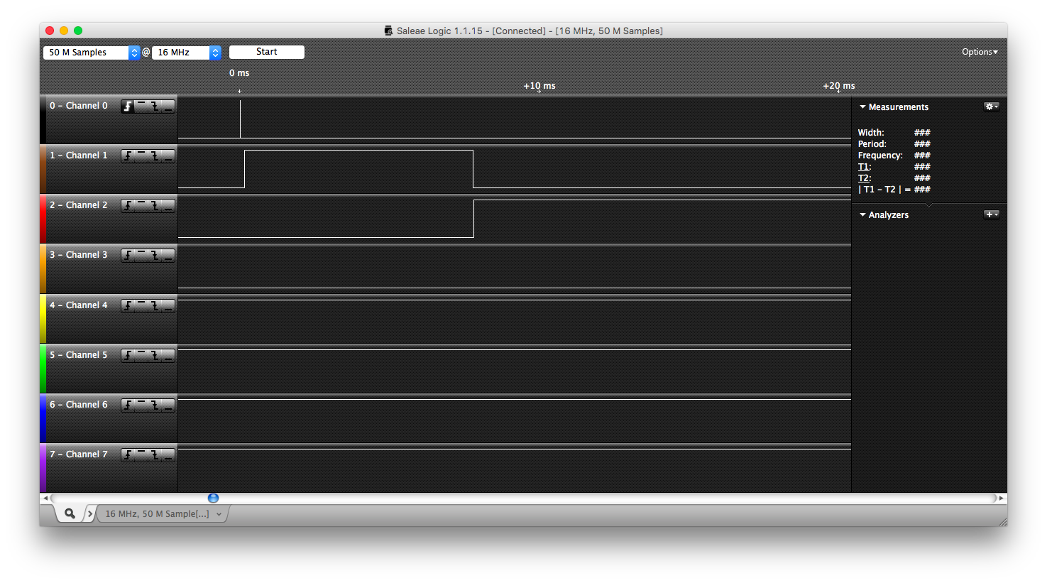
| Objective: | This test shows that if P1 signals an event, then P2 reaches that event, it will set the flag back to 0 and continue running because the signal has already been sent. |
The message sequence chart is shown here:
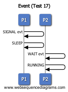
| Results: | As shown in the screen capture below, our results are consistent with the message sequence charts expected running order of P1, P2. |
 Test 3
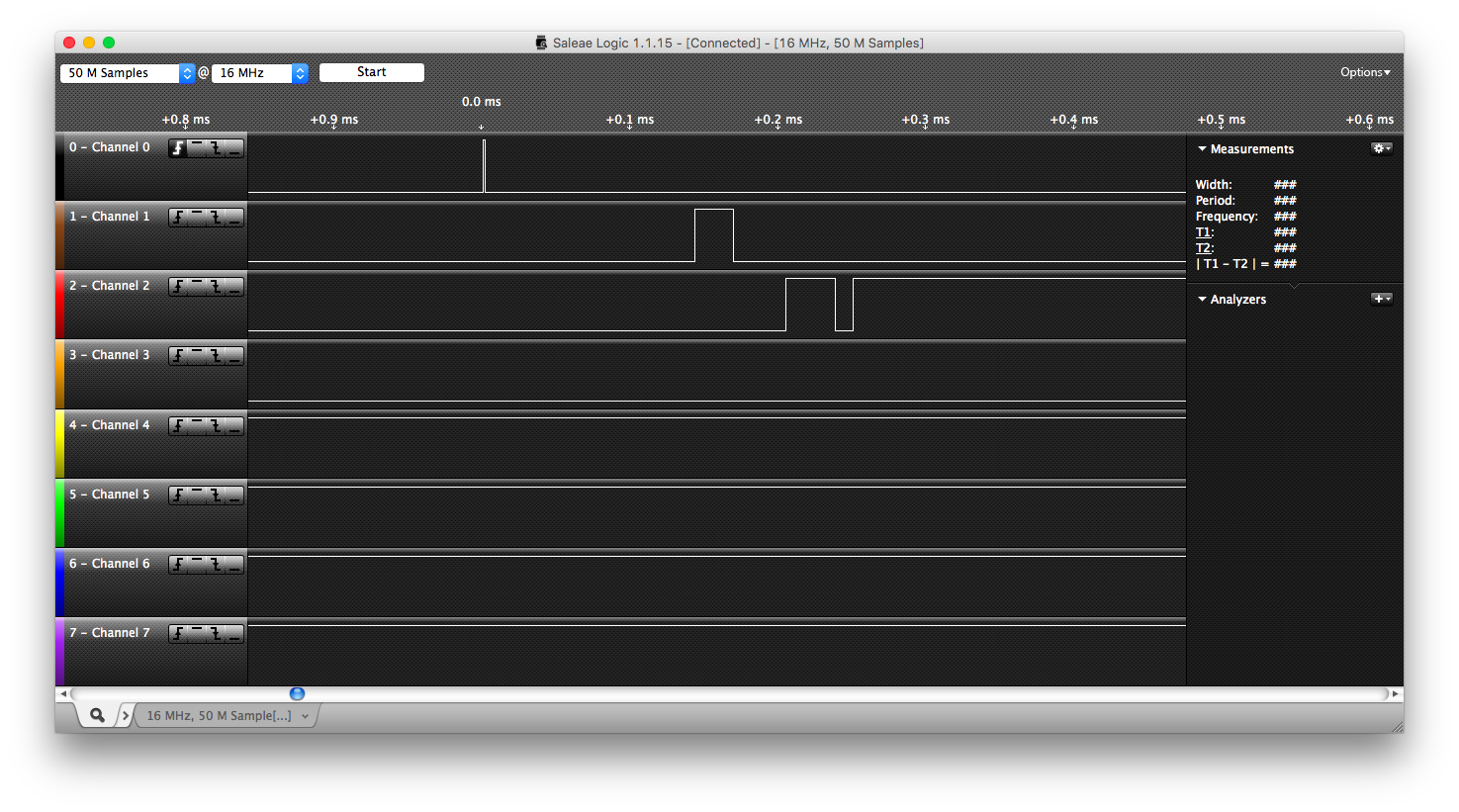
| Objective: | This test shows that only one task can wait on an event at a time. P1 will wait on an event, then P2 will call Event_Wait on the same event but continue running. |
The message sequence chart is shown here:
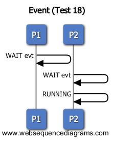
| Results: | As shown in the screen capture below, our results are consistent with the message sequence charts expected running order of P1, P2. |
RTOS Performance Measurements
Performance measurements were collected using a USB logic analyzer and setting a pin high when entering the specific piece of code to be instrumented. The pin would then be set low when the desired piece of code had finished executing. The following sections show the logic analyzer outputs and measured times:
Boot Time
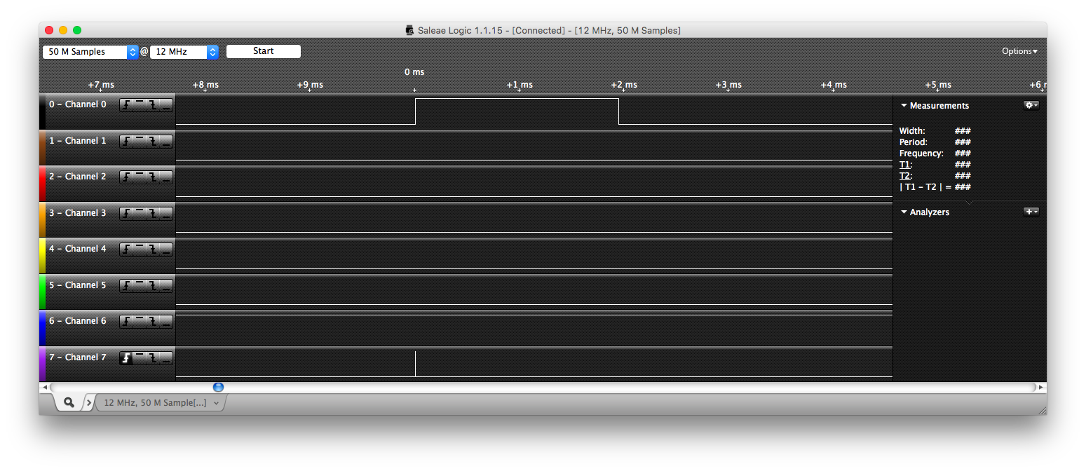 The boot time refers to the amount of time it takes for the RTOS to initialize and start.
| Channel 0 | Boot Time = 1.942 ms |
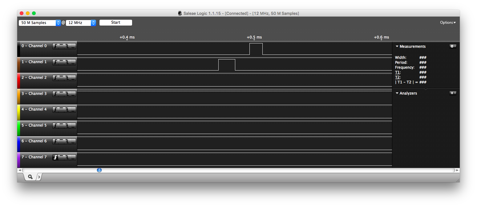 The dispatch time refers precisely to the dispatch function discussed above and measures the amount of time it takes to select a new task from the ReadyQueue to run. The context switching time is the time it takes to save the current context onto the stack, and restore a new context back into the registers. The time is the same for entering the kernel, or leaving the kernel.
| Channel 0 | Dispatch = 10.17 μs |
| Channel 1 | Context Switch = 13 μs |
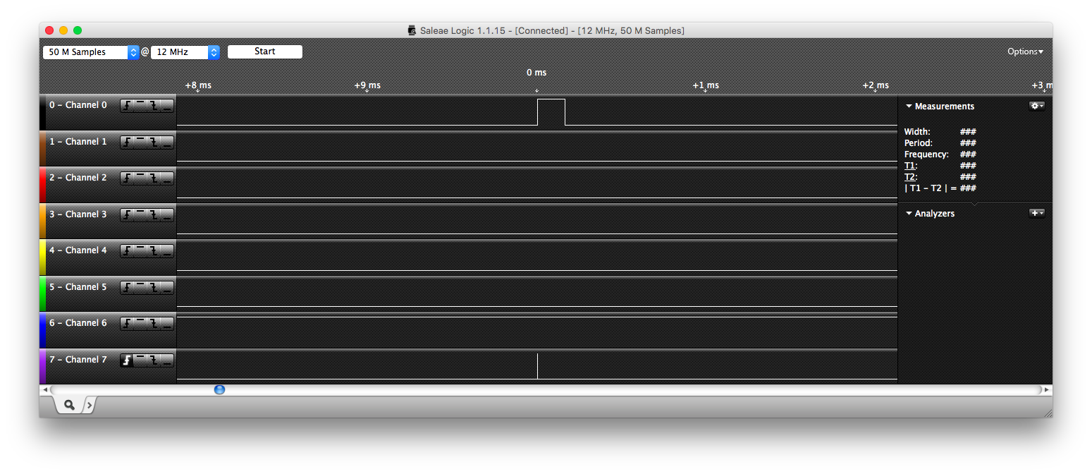 The worst case interrupt disabled time is measured as the longest time interrupts are disabled. This happens when a call to Task_Create occurs. We enter the kernel, create the task, and return back to the original task (if the original task still has the highest priority).
| Channel 0 | Worst Case Interrupt Disabled Time = 0.163 ms |
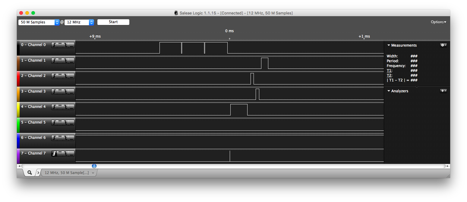 The following table shows the average times for each of the actions that can take place on a task:
| Channel 0 | Task Create = 0.15 ms |
| Channel 1 | Task Sleep = 56.17 μs |
| Channel 2 | Task Suspend = 23.58 μs |
| Channel 3 | Task Resume = 24.33 μs |
| Channel 4 | Task Terminate = 0.12 ms |
| Not Displayed | Task GetArg = 0.12 μs |
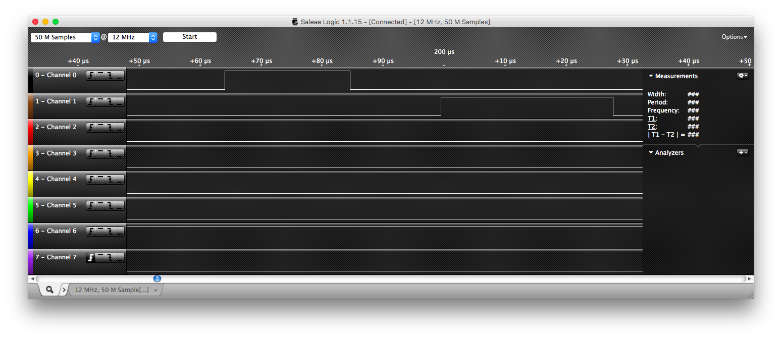 The following table shows the average times for each of the actions that can take place on a mutex:
| Channel 0 | Mutex Lock = 20.5 μs |
| Channel 1 | Mutex Unlock = 28.17 μs |
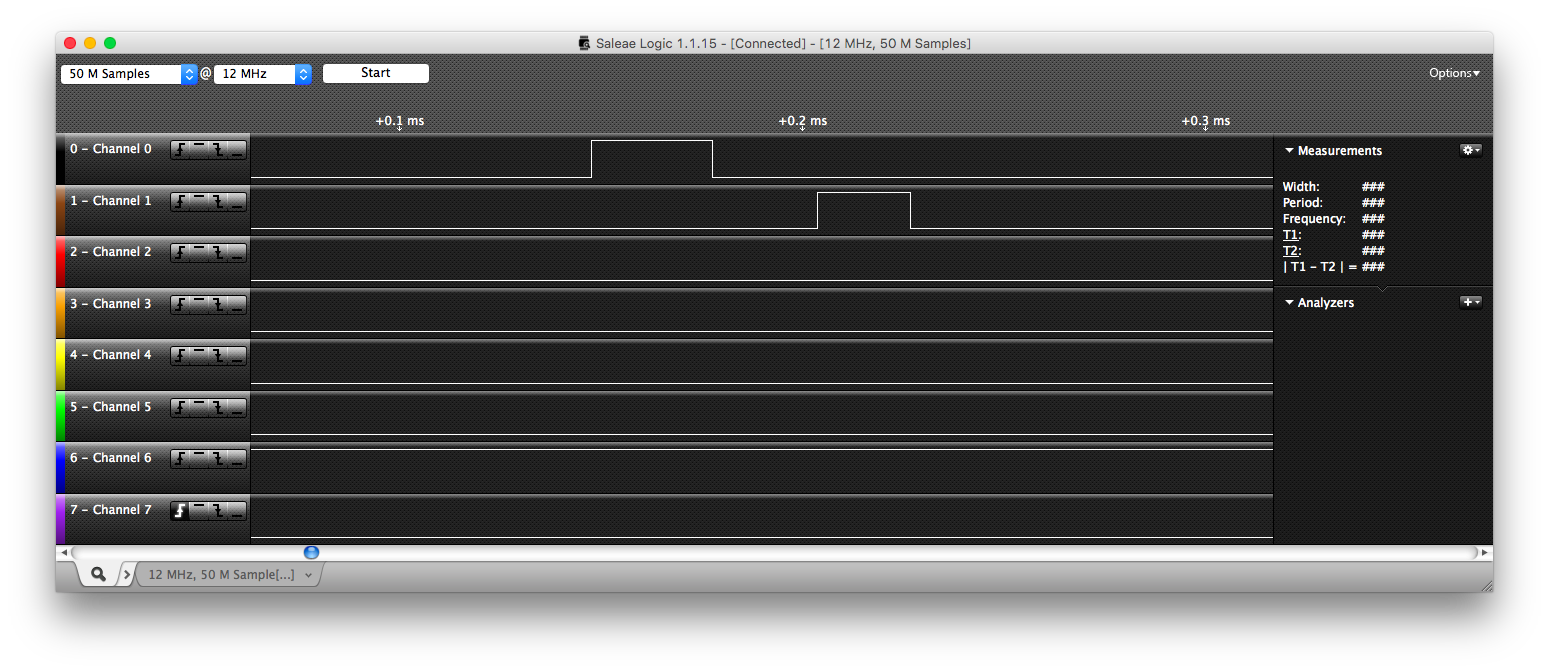 The following table shows the average times for each of the actions that can take place on an event:
| Channel 0 | Event Wait = 30 μs |
| Channel 1 | Event Signal = 23 μs |
Future Improvements
Improve Interrupt Service Routine
Currently the interrupt service routine (ISR) fires every 10 ms to check the SleepQueue and potentially dispatch a new task. Currently if a new task is dispatched, the ISR does not finish its execution and leaves a return address on the stack. One improvement to this is to instead use the eijmp (extended indirect jump) instruction to leave the ISR and enter the kernel without leaving a return address on the stack. This would slightly improve performance and make sure the ISR finishes its execution.
Reduce CPU Power Consumption
A way to improve the battery life of any applicaiton running on this RTOS is to put the CPU into a low power mode if there is no task to execute. This can be done using the AVR sleep library. The idea would be to find a way to estimate how long the CPU plans to be idle, and if it was worth it, sleep for that amount of time. Calculations would have to be performed to detemine the overhead of putting the CPU to sleep and waking it up. With that information, an informed decision could be made to sleep the CPU if it is going to be idle for more than t milliseconds.
Improving Core RTOS Performance
Other cleanup and improvements for this RTOS include improving the queue data structure. Currently, either one of dequeue or enqueue is an O(n) operation, while the other is O(1). They can both be made O(1) operations by revising the queueing/dequeueing strategy or using a hash table instead.
Conclusion
The goal going forward is to incorporate the RTOS designed and implemented here into project 3 which will see the successful completion of a roomba tank. The work above shows that the RTOS is functional, passes a wide range of test cases with maximum coverage, has good performance, and gives us confidence going into project 3.
References
Appendix
Initial Test 1 Zoomed Captures
Initial Test 2 Zoomed Captures
Initial Test 3 Zoomed Captures
Initial Test 4 Zoomed Captures
Code
Download the project 2 source code here.